Rotary locking type hydraulic damping sucking disk device

A hydraulic shock absorption and locking technology, which is applied in the direction of spring/shock absorber, non-rotational vibration suppression, suction cup, etc., can solve the problems of low suction cup adsorption capacity, laborious operation of suction cup, uneven force, etc., to achieve simple operation, The effect of reducing the operation process and reducing the probability of damage

Pending Publication Date: 2018-05-29
JILIN UNIV
View PDF0 Cites 5 Cited by
  • Summary
  • Abstract
  • Description
  • Claims
  • Application Information

AI Technical Summary

Problems solved by technology

[0005] The invention aims at the problems of low suction capacity of the suction cup, laborious operation of releasing the suction cup,

Method used


Image

  • Rotary locking type hydraulic damping sucking disk device
  • Rotary locking type hydraulic damping sucking disk device
  • Rotary locking type hydraulic damping sucking disk device

Examples


Example Embodiment

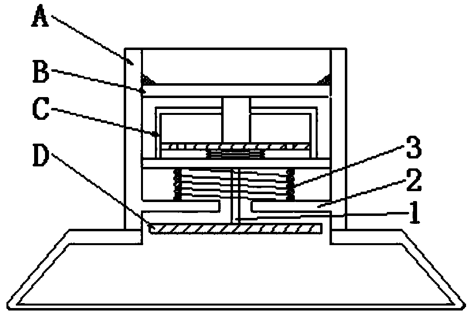
[0041] Such as figure 1 As shown, the present invention is composed of suction cup assembly A, pressing knob B, hydraulic assembly C, sealing assembly D and spring I3, wherein pressing knob B, hydraulic assembly C, spring I3 and sealing assembly D are in the hollow cylinder 4 of suction cup assembly A Arranged from top to bottom, the cylindrical surface of the tappet 17 in the pressing knob B is slidably connected with the central hole Ⅱ 18 on the cover of the cylinder block 16 in the hydraulic assembly C and is slidingly sealed with the central hole Ⅱ 18. The lower end of the tappet 17 and the hydraulic assembly C The upper center of the middle buffer plate 13 is fixedly connected.

[0042] The outer edges of the three flanges 10 of the pressure plate 9 in the pressing knob B are slidingly connected to the inner wall of the hollow cylinder 4 of the suction cup assembly A, and the three flanges 10 of the pressure plate 9 in the pressing knob B are covered by the hollow cylinder 4 ...


PUM


Abstract

The invention discloses a rotary locking type hydraulic damping sucking disk device, and belongs to the technical field of sucking disk absorption. A cylinder face in a tappet of a rotary button is glidingly connected with a center hole II on a cover of a cylinder body in a hydraulic component, the lower end of the tappet is fixedly connected to the center above a buffer plate; outer edges of three convex edges of a pressing plate are glidingly connected with the inner wall of a hollow cylinder of the sucking disk component, the edge of a bottom plate in the hydraulic component is glidingly connected to the inner wall of the hollow cylinder of the sucking disk component; the upper end of a support pillar in the sealing component is fixedly connected to the lower center of the bottom platein the hydraulic component, the cylinder of the supporting pillar in the sealing component is glidingly connected with the center hole I of the round disk in the sucking disk component; a spring I isplaced between the bottom plate of the hydraulic component and the round disk of the sucking disk component. The rotary locking type hydraulic damping sucking disk device has good absorption and buffer performances, and is simple in structure, small in volume, convenient to operate, and can be widely applied to production and daily life.

Description

technical field [0001] The invention belongs to the technical field of sucker adsorption, and in particular relates to a rotary locking type hydraulic shock-absorbing sucker device. Background technique [0002] With the continuous upgrading of industrial intelligence and automation, more and more enterprises are gradually replacing traditional manual production methods by adopting automated production equipment. As a terminal actuator widely used in the field of automation, vacuum suction cups are widely used. With the increasing penetration of automated production methods into all walks of life, the demand for different functions and types of automation equipment is increasing, resulting in a matching demand for vacuum suction cups of different materials, shapes and sizes. [0003] From the current point of view, the existing suction cups that are widely used in a large range have the advantages of simple adsorption principle, convenient use, and low production cost, but ...

Claims


Application Information

Patent Timeline
IPC IPC(8): F16B47/00F16F15/023F16F15/04
CPCF16B47/00F16F15/022F16F15/023F16F15/04
Inventor 丛茜熙鹏范加祥
Owner JILIN UNIV
Why Eureka
Try Eureka