A precise gas concentration control device for injection-assisted sintering method and its control method

A technology of injection device and control device, which is applied to furnace control device, furnace, lighting and heating equipment, etc., can solve problems such as energy waste, explosion production accident, increase of gas burning point, etc., to improve the degree of freedom and adjustability , The effect of improving the adaptability of the device and reducing the energy consumption index

Active Publication Date: 2020-12-04
ZHONGYE-CHANGTIAN INT ENG CO LTD
View PDF9 Cites 0 Cited by
  • Summary
  • Abstract
  • Description
  • Claims
  • Application Information

AI Technical Summary

Problems solved by technology

[0005] However, the injection-assisted sintering method under the existing technology lacks an effective and precise control method for the gas concentration on the material surface. When the sintering machine operating conditions fluctuate during production, the injection parameters cannot be adjusted in time to ensure that the gas concentration on the material surface is within a reasonable range. , it is easy to cause the following results:
[0006] 1. The gas concentration on the material surface is too high: When the gas concentration on the material surface of the sintering machine is too high during production, the combustion point of the gas will decrease accordingly, which will make the gas pumped into the material layer start before reaching the predetermined position. Combustion, thus forming two combustion zones in the material layer, making the gas injection assisted sintering technology meaningless; in addition, once the gas concentration on the material surface is higher than the lower limit concentration value of the gas explosion, it is very easy to form an explosion and cause serious production accidents;
[0007] 2. The gas concentration on the material surface is too low: When the gas concentration on the material surface of the sintering machine is too low during production, the combustion point of the gas will increase accordingly, and may even be higher than the temperature of the combustion zone in the sintering material layer. At this time, the gas will not Instead of being ignited, it is directly pumped away through the sinter layer from top to bottom, resulting in serious energy waste, and at the same time, the injection auxiliary technology cannot achieve the effect

Method used


Image

  • A precise gas concentration control device for injection-assisted sintering method and its control method
  • A precise gas concentration control device for injection-assisted sintering method and its control method
  • A precise gas concentration control device for injection-assisted sintering method and its control method

Examples


Embodiment 1

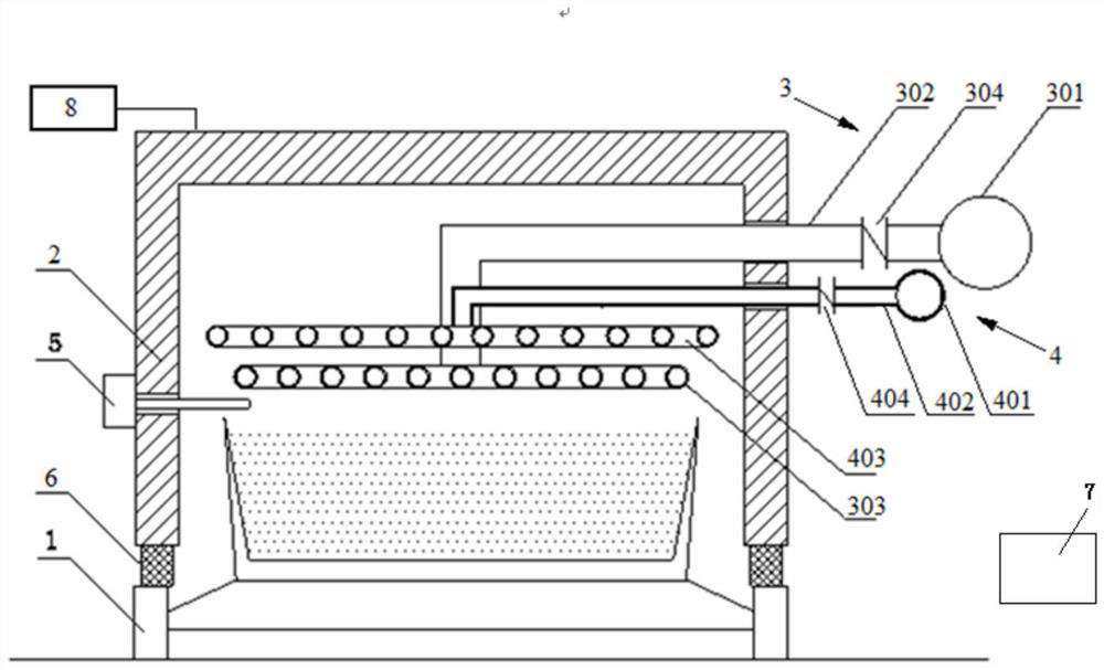
[0080] A precise gas concentration control device for injection-assisted sintering, comprising a sintering machine trolley 1 and an injection hood 2 . The blowing cover 2 is located on the upper part of the sintering machine trolley 1 and forms a sealed body with the sintering machine trolley 1 . The device also includes a gas injection device 3 and a material level CO detection device 5 arranged on the injection hood 2 . The gas injection device 3 includes a gas injection main pipe 301, 6 gas injection branch pipes 302 and a gas injection pipe row connected with each gas injection branch pipe 302 by 12 gas injection pipes 303 arranged in parallel. The gas injection main pipe 301 is arranged on the outside of the blowing hood 2. One end of the gas injection branch pipe 302 is connected to the gas injection main pipe 301 and the other end is connected to 12 gas injection pipes 303. The gas injection branch pipe 302 extends into the blowing cover 2. The material level CO detect...

Embodiment 2

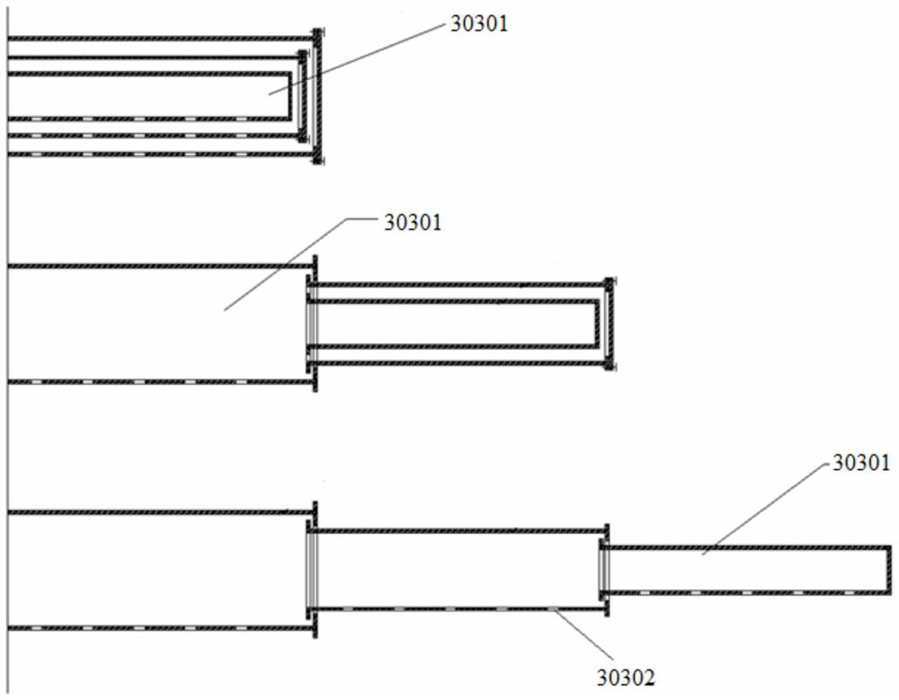
[0082] Repeat Example 1, except that the gas injection pipe 303 is a 3-section gas injection sleeve 30301. The air blowing pipe 403 is a 3-section air blowing sleeve 40301.

Embodiment 3

[0084] Embodiment 1 is repeated, except that the gas injection main pipe 301 is provided with eight gas injection branch pipes 302 . Eight gas injection pipes 303 are arranged on one side of each gas injection branch pipe 302 . The main air blowing pipe 401 is provided with eight air blowing branch pipes 402 . Eight air blowing pipes 403 are arranged on one side of each air blowing branch pipe 402 .


PUM


Abstract

A fuel concentration accurate control device for a blowing auxiliary sintering method comprises a sintering machine trolley (1) and a blowing cover (2). The blowing cover (2) is located on the upper portion of the sintering machine trolley (1) and combines into a sealing body with the sintering machine trolley (1). The fuel concentration accurate control device is characterized in that the devicefurther comprises a fuel blowing device (3) and a material face detecting device (5) which are arranged on the blowing cover (2), the fuel blowing device (3) comprises a fuel blowing master pipe (301), a fuel blowing branch pipe (302) and a fuel blowing pipe (303), and the material face CO detecting device (5) penetrates through the blowing cover (2), is located above the sintering machine trolley(1) and is lower than the fuel blowing pipe (303). According to the fuel concentration accurate control device, the material face fuel volume concentration value can be rapidly detected and controlled when the work condition is changed and thus fluctuation occurs, and thus returns to the normal range, and thus it is effectively guaranteed that disadvantageous condition that the material face fuelvolume concentration is over high or over low for a long time in the production process can be avoided.

Description

technical field [0001] The invention belongs to the technical field of metallurgical sintering equipment, and in particular relates to a precise gas concentration control device and a control method for an injection-assisted sintering method. Background technique [0002] The sintering process is a key link in the ironmaking process. Its principle is to mix various powdery iron-containing raw materials with an appropriate amount of fuel and flux, add an appropriate amount of water, mix and pelletize the material on the sintering equipment to make the material A series of physical and chemical changes, sintered into blocks, which are sent to the blast furnace for the next step. [0003] In order to reduce the coke ratio and smelting cost of blast furnace ironmaking, blast furnaces often require high strength and high reducibility for sinter. In the sintering process, the sintered ore is generally required to have high strength, high yield, low return rate, and low fuel consu...

Claims


Application Information

Patent Timeline
Patent Type & Authority Patents(China)
IPC IPC(8): F27B21/14F27D19/00C22B1/16
CPCC22B1/16F27B21/00F27D19/00F27D2019/004
Inventor 周浩宇魏进超李俊杰
Owner ZHONGYE-CHANGTIAN INT ENG CO LTD
Why Eureka
Try Eureka