
Encoder and signal processing circuit

A technology of encoders and circuits, applied in the field of encoders and signal processing circuits, can solve the problems of power supply voltage changes, position detection accuracy reduction, etc., and achieve the effect of highly accurate position detection

Inactive Publication Date: 2018-05-29
MITUTOYO CORP
View PDF9 Cites 1 Cited by
  • Summary
  • Abstract
  • Description
  • Claims
  • Application Information

AI Technical Summary

Problems solved by technology

Therefore, there may be effects from variations in supply voltage
As described above, even in the configuration corresponding to the four-phase signal, although the output voltage for each phase can be made constant, the reference voltage REF (to which the output voltage is compared during the arithmetic operation) varies, and thus due to the arithmetic Decrease in position detection accuracy due to difference in operation timing is inevitable

Method used


Image

  • Encoder and signal processing circuit
  • Encoder and signal processing circuit
  • Encoder and signal processing circuit

Examples


no. 1 example

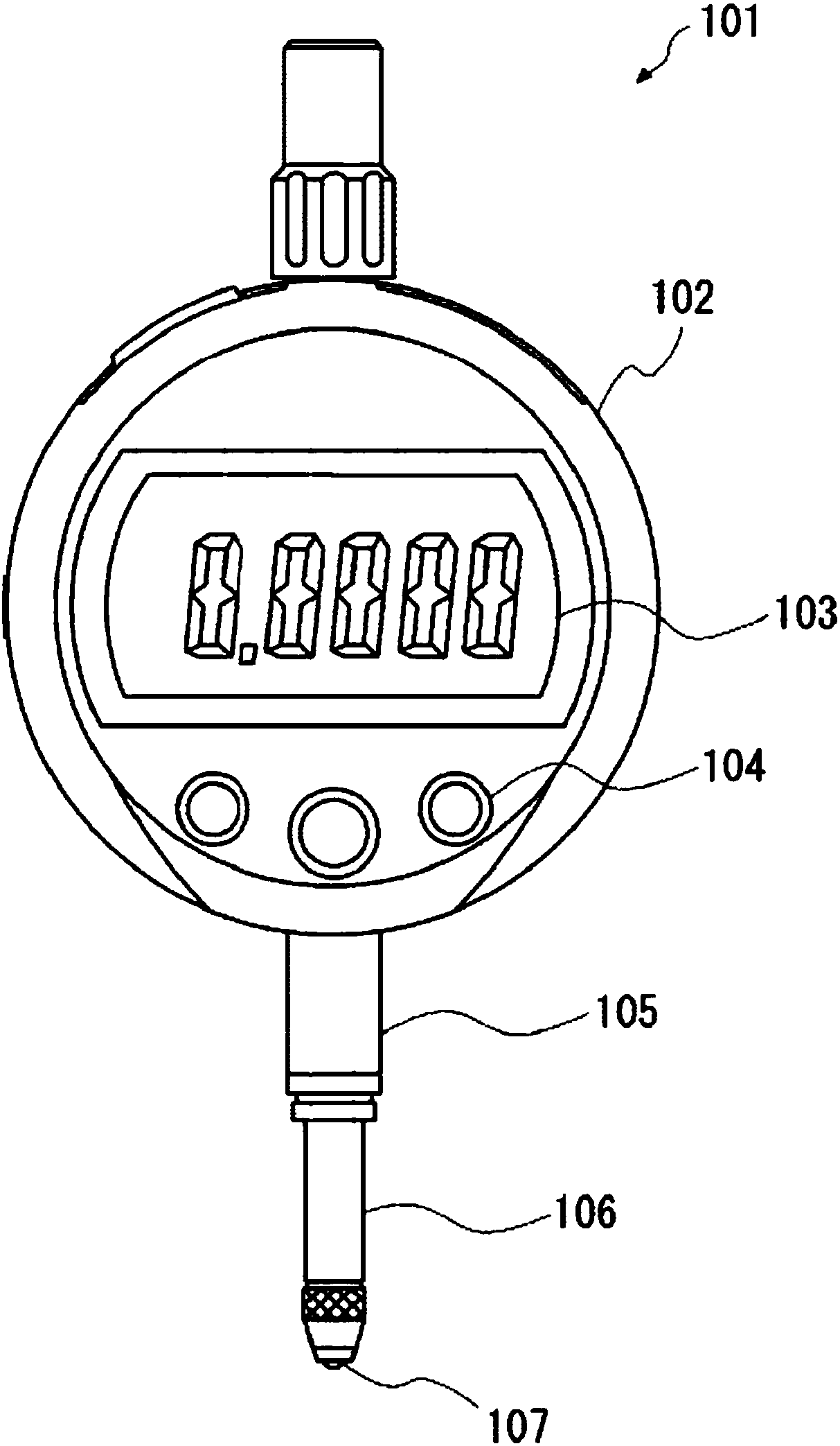
[0052] The optical encoder according to the first embodiment is described. figure 1 It is a front view schematically illustrating the configuration of the dial gauge 101 incorporating an optical encoder according to the first embodiment. The dial indicator 101 includes a main body 102, a display 103, an operation button 104, a stem 105, a spindle 106, a stylus head 107 and an output port 108.

[0053] The main body 102 has a substantially circular cylindrical shape, wherein figure 1 The vertical height of the drawing plane is less than figure 1 The horizontal width of the drawing plane. A display 103 that displays, for example, a measured value is provided on one surface of the main body 102.

[0054] The valve stem 105 has a substantially cylindrical shape, and is provided so as to protrude from the outer edge of the main body 102.

[0055] The main shaft 106 is a substantially cylindrical member inserted through the valve stem 105 and supported so as to be able to slide in the ...


PUM


Abstract

A reference voltage generator circuit generates a reference voltage corresponding to a power supply voltage. A current / voltage converter circuit converts a photocurrent output by a photoreceiver intovoltage, and outputs a voltage obtained by adding the converted voltage and the reference voltage. A sample and hold circuit holds a voltage of a capacitor in response to a sample and hold signal, thecapacitor having the voltage input at one end and the reference voltage input at another end. An amplifier circuit outputs an output signal where a voltage held by the sample and hold circuit is amplified with the reference voltage as a reference.

Description

[0001] Cross references to related applications [0002] This application claims priority of Japanese Application No. 2016-226888 filed on November 22, 2016, and the disclosure of this application is expressly incorporated herein by reference in its entirety. Technical field [0003] The invention relates to an encoder and a signal processing circuit. Background technique [0004] The encoder is installed in a displacement measuring device such as a dial gauge or indicator to measure the amount of displacement. A known example of such an encoder is an optical encoder that uses optical interference to measure the amount of displacement. In addition, encoders are roughly classified into incremental encoders that measure relative displacement and absolute encoders that detect absolute positions. For example, the specification of Japanese Patent No. 5,771,070 proposes a configuration for an absolute type optical encoder. [0005] In the exemplary optical encoder, illuminating light fro...

Claims


Application Information

Patent Timeline
Patent Type & Authority Applications(China)
IPC IPC(8): G01D5/26G01B11/02
CPCG01B11/02G01D5/26G01D5/24428G01D5/34715G01D5/34746G11C27/026G01D5/38G01D5/34707
Inventor 川床修田原智弘小林博和
Owner MITUTOYO CORP
Learn More