Obstacle information acquisition method, laser pulse emission method and device

A technology of laser pulse and emission device, applied in the field of environmental perception, to solve the blind spot of measurement, low cost, and ensure the effect of normal detection

Active Publication Date: 2020-04-24
HESAI TECH CO LTD
View PDF9 Cites 26 Cited by
  • Summary
  • Abstract
  • Description
  • Claims
  • Application Information

AI Technical Summary

Problems solved by technology

[0005] The technical problem solved by the embodiments of the present invention is how to solve the problem of the measurement blind area of ​​near-field obstacles caused by stray light inside the lidar at a lower cost

Method used


Image

  • Obstacle information acquisition method, laser pulse emission method and device
  • Obstacle information acquisition method, laser pulse emission method and device
  • Obstacle information acquisition method, laser pulse emission method and device

Examples


Embodiment Construction

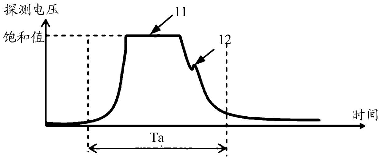
[0032] In the existing laser radar system, since the emitted laser pulse is directly absorbed by the APD, the detection circuit is saturated, thus submerging the laser pulse echo signal reflected by the near-field obstacle, forming a measurement blind area, such as figure 1 shown.

[0033] see figure 1 , when the laser radar emits a laser pulse, the voltage signal detected by the APD includes: the emitted laser pulse is directly absorbed by the APD, that is, the voltage signal 11 that the stray light causes the detection circuit to saturate, and the laser pulse reflected by the near-field obstacle The wave signal 12, because the stray light directly absorbed by the APD causes the detection circuit to saturate, so the voltage signal 11 is equal to the voltage saturation value, which is greater than the laser pulse echo signal 12 emitted by the obstacle in the near field, thus causing the echo signal 12 to be submerged , the distance information of near-field obstacles cannot b...


PUM


Abstract

A method for obtaining obstacle information, a laser pulse emitting method and a device, the laser pulse emitting method includes: emitting a first laser pulse at a first moment; emitting a second laser pulse at a second moment, the first laser pulse The peak power of a laser pulse is less than the peak power of the second laser pulse, and the time interval between the second moment and the first moment is greater than T, where T is the moment when the laser pulse is emitted and the reflection of the near-field obstacle is received The duration between the moments of the laser pulse echo signal. Applying the above scheme, since the power of the first laser pulse is small, stray light will not cause the voltage saturation of the detection circuit, so the first laser pulse reflected by the near-field obstacle can be detected, thereby effectively solving the problem of laser light at a lower cost. The measurement blind area of ​​near-field obstacles caused by stray light inside the radar; at the same time, due to the strong second laser pulse signal, the normal detection of far-field obstacles can be guaranteed.

Description

technical field [0001] The embodiments of the present invention relate to the field of environment perception technologies, and in particular to a method for obtaining obstacle information, a method and a device for emitting laser pulses. Background technique [0002] Since the shape and distance information of all obstacles within 100 meters of the vehicle can be obtained, lidar has become a necessary sensor for automatic driving. In the current laser radar system, the method of pulse ranging is mainly used to obtain obstacle information, that is, by emitting laser pulses with narrow pulse width and high peak power, and then measuring the reflection with an avalanche photodiode detector (Avalanche Photo Diode, APD). The time delay of the pulse, so as to calculate the distance information of the obstacle. [0003] For the lidar system using the pulse ranging method, during the transmission of optical pulses, a small part of the transmitted pulses will be directly received b...

Claims


Application Information

Patent Timeline
Patent Type & Authority Patents(China)
IPC IPC(8): G01S17/931G01S7/484G01S17/10
CPCG01S7/484G01S17/931G01S17/10G01S7/4868G01S7/4818
Inventor 潘政清向少卿李一帆
Owner HESAI TECH CO LTD
Why Eureka
Try Eureka