
Device and method for detecting fault position of multi-mode optical fiber by using optical resonant cavity

A multi-mode optical fiber, fault location technology, applied in the direction of measuring devices, using re-radiation, re-radiation of electromagnetic waves, etc., can solve the problems of complex structure, high equipment requirements, and inability to meet at the same time

Pending Publication Date: 2021-05-18
TAIYUAN UNIV OF TECH +1
View PDF0 Cites 0 Cited by
  • Summary
  • Abstract
  • Description
  • Claims
  • Application Information

AI Technical Summary

Problems solved by technology

[0005] In order to solve the problem that the pulse method measurement cannot satisfy both long-distance and high precision in multi-mode optical fiber fault position detection, and the chaotic optical time-domain reflection measurement method has a complex structure and high requirements for equipment, the present invention provides a method using light Resonant cavity realizes detection device and method of multimode optical fiber fault location

Method used


Image

  • Device and method for detecting fault position of multi-mode optical fiber by using optical resonant cavity

Examples


Embodiment Construction

[0013] The present invention will be further described below in conjunction with specific examples.

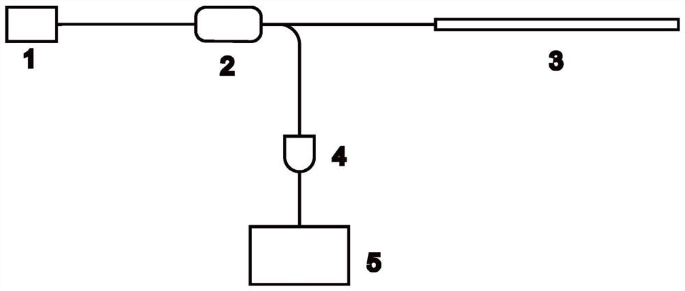
[0014] A detection device that utilizes an optical resonant cavity to realize the fault location of a multimode optical fiber, such as figure 1 As shown: it includes a semiconductor laser 1, a single-mode fiber coupler 2, a photodetector 4 and an oscilloscope 5. The semiconductor laser 1 itself does not have an isolator and has its own single-mode pigtail; the single-mode fiber coupler 2 Both ends are equipped with single-mode pigtails; the semiconductor laser 1 is connected to the left side of the single-mode fiber coupler 2 through the self-contained single-mode pigtails, and the one on the right side of the single-mode fiber coupler 2 A single-mode pigtail is connected to the multimode optical fiber 3 to be tested, and another single-mode pigtail is connected to the photodetector 4, and the photodetector 4 is connected to the oscilloscope 5 through a transmission cable, and...


PUM

PropertyMeasurementUnit
Diameteraaaaaaaaaa

Abstract

The invention discloses a device and a method for detecting a fault position of a multi-mode optical fiber by using an optical resonant cavity, and relates to the technical field of optical fiber fault detection. According to the technical scheme, laser light emitted by a semiconductor laser enters a single-mode optical fiber coupler, output light passes through an upper branch and a lower branch respectively, light in the upper branch enters a multi-mode optical fiber to be detected, the light returns after Fresnel reflection at a fault point, part of the light on the left end face of the optical fiber to be detected returns to the single-mode optical fiber coupler and then returns to the semiconductor laser to generate chaotic laser, and the other part of light is subjected to Fresnel reflection on the left end face of the multi-mode optical fiber to be detected and then reaches the fault point of the optical fiber to be measured again, so that the left end face of the multi-mode optical fiber and the fault point form an optical resonant cavity, the process is repeated in the optical fiber to be detected to generate resonance, the lower branch of the single-mode optical fiber coupler is connected with a photoelectric detector and then connected with an oscilloscope for detection and self-correlation operation, and the position of a resonance peak in self-correlation is the distance between the left end face of the multi-mode optical fiber to be detected and the fault position. According to the detection method, the fault of a multi-mode optical fiber can be rapidly and accurately measured, the detection has no blind area, and the structure is simple.

Description

technical field [0001] The invention relates to the technical field of optical fiber fault detection, in particular to a detection device and method for realizing the fault location of a multimode optical fiber by using an optical resonant cavity. Background technique [0002] Since multimode fiber has a larger core diameter, which means it supports more transmission modes, it is inseparable from the participation of multimode fiber in short-range local area networks, data centers, laser ignition, engineering applications and experiments. However, during use, multimode fiber will cause information transmission failure and ignition failure due to fiber contamination and fiber connection failure, and even cause serious damage and loss. Therefore, the fault detection of multimode fiber becomes more and more important. . [0003] At present, multimode optical fiber fault detection is usually measured by the pulse-of-flight method. The typical measuring instrument is an optical ...

Claims


Application Information

Patent Timeline
IPC IPC(8): G01S17/06
CPCG01S17/06
Inventor 王安帮潘通贺爱锋井波张晶鑫曹椿强刘虎王云才赵彤张建国
Owner TAIYUAN UNIV OF TECH
Learn More