Process chamber

A process chamber and chamber technology, applied in the field of process chambers, can solve the problems of low product yield, uneven process air intake, low wafer transfer efficiency, etc., so as to improve equipment productivity, process synchronization, and process time. shortening effect

Active Publication Date: 2018-05-29
BEIJING NAURA MICROELECTRONICS EQUIP CO LTD
View PDF10 Cites 0 Cited by
  • Summary
  • Abstract
  • Description
  • Claims
  • Application Information

AI Technical Summary

Problems solved by technology

[0008] Aiming at the above-mentioned deficiencies in the prior art, the present invention provides a process chamber to solve the problems of low film transfer efficiency, uneven process air intake, and low product yield

Method used


Image

  • Process chamber
  • Process chamber
  • Process chamber

Examples


Embodiment Construction

[0045] The technical solutions in the present invention will be clearly and completely described below in conjunction with the accompanying drawings in the present invention. Apparently, the described embodiments are part of the embodiments of the present invention, not all of them. Based on the embodiments of the present invention, all other embodiments obtained by persons of ordinary skill in the art without making creative efforts belong to the protection scope of the present invention.

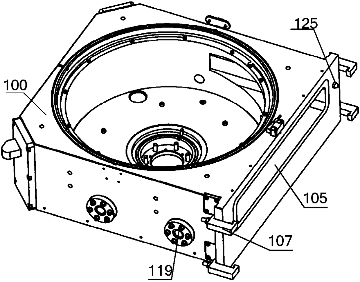
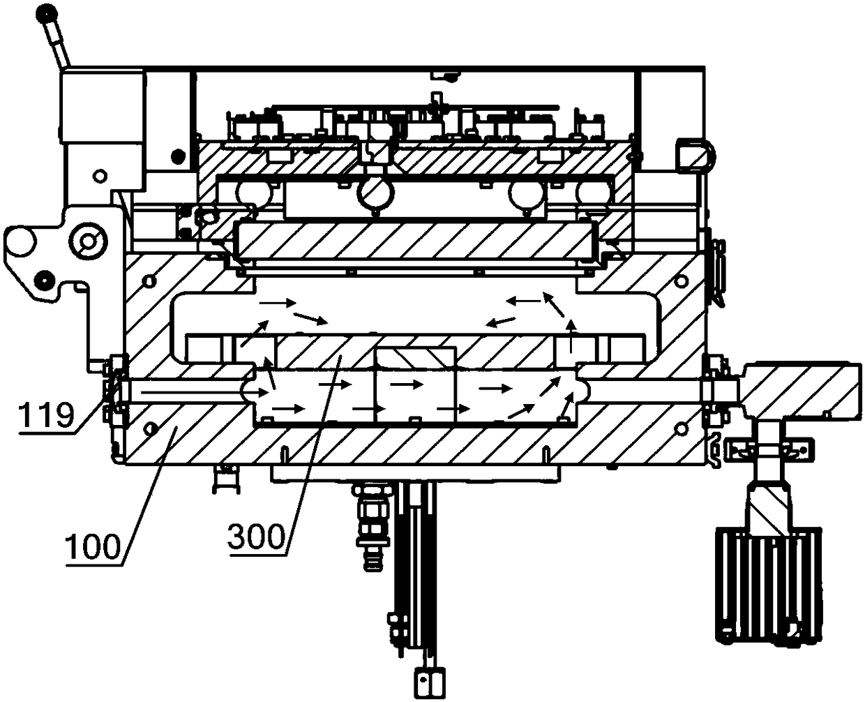
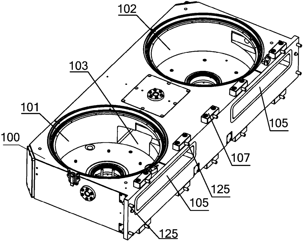
[0046] In the embodiment of the present invention, by introducing an integrated dual-chamber structure, the dual-chamber parallel processing function is realized, the process efficiency is improved, and the production capacity of the equipment is increased. By setting the air intake channel on the chamber body, the process gas is introduced into the upper part of the heater in the two chambers at the same time, and the uniform flow hole structure on the air intake ring is used to achieve un...


PUM


Abstract

The invention provides a process chamber. A first chamber and a second chamber which are identical in structure and symmetrically arranged are arranged on the chamber body, and a connecting cavity forhorizontally connecting the first chamber and the second chamber is arranged on the chamber body so that two wafers can be simultaneously transmitted into the first chamber and the second chamber, and thus half of the wafer transmission time can be shortened and the wafer transmission efficiency and the equipment productivity can be enhanced.

Description

technical field [0001] The invention relates to the technical field of semiconductor equipment manufacturing, in particular to a process chamber. Background technique [0002] With the rapid development of the integrated circuit market, the demand for chip production capacity expansion has brought new market opportunities to equipment manufacturers on the one hand, and on the other hand, it has also put forward higher requirements on the existing and forward-looking technical capabilities of equipment manufacturers. Equipment capacity refers to the output of good products per unit working time of the equipment, which is an important technical parameter reflecting the processing capacity of the equipment. The degassing equipment and annealing equipment used in integrated circuit manufacturing need to use the manipulator to cooperate with the lifting mechanism of the process chamber to complete the transfer of the wafer before performing the corresponding process. How to impr...

Claims


Application Information

Patent Timeline
Patent Type & Authority Applications(China)
IPC IPC(8): H01L21/67
CPCH01L21/67109H01L21/67173H01L21/67207H01L21/67H01L21/677
Inventor 邓玉春邱国庆赵梦欣
Owner BEIJING NAURA MICROELECTRONICS EQUIP CO LTD
Why Eureka
Try Eureka