Friction power generation device

A technology of friction power generation and friction layer, which is applied in the direction of friction generators, etc., can solve the problems of unfavorable system integration and limit the application area of ​​friction generators, achieve high array density, solve the difficulties of small-area application, and increase the effect of friction area

Active Publication Date: 2018-05-29
CHINA UNIV OF GEOSCIENCES (BEIJING)
View PDF1 Cites 4 Cited by
  • Summary
  • Abstract
  • Description
  • Claims
  • Application Information

AI Technical Summary

Problems solved by technology

However, with the development of microelectronics and microsystem technology, electronic devices and functional sensors are becoming more and more miniaturized, which limits the application area of ​​tribogenerators. high demands
[0003] In the prior art, triboelectric devices generally set the friction interface parallel to the plane where the device is located. This parallel friction interface has high requirements for the application area. In order to increase the output voltage, it is often necessary to lay a large-area friction generator, which is not conducive to system integration

Method used


Image

  • Friction power generation device
  • Friction power generation device
  • Friction power generation device

Examples


Embodiment Construction

[0026] The following will clearly and completely describe the technical solutions in the embodiments of the present invention with reference to the accompanying drawings in the embodiments of the present invention. Obviously, the described embodiments are some of the embodiments of the present invention, but not all of them. Based on the embodiments of the present invention, all other embodiments obtained by persons of ordinary skill in the art without making creative efforts belong to the protection scope of the present invention.

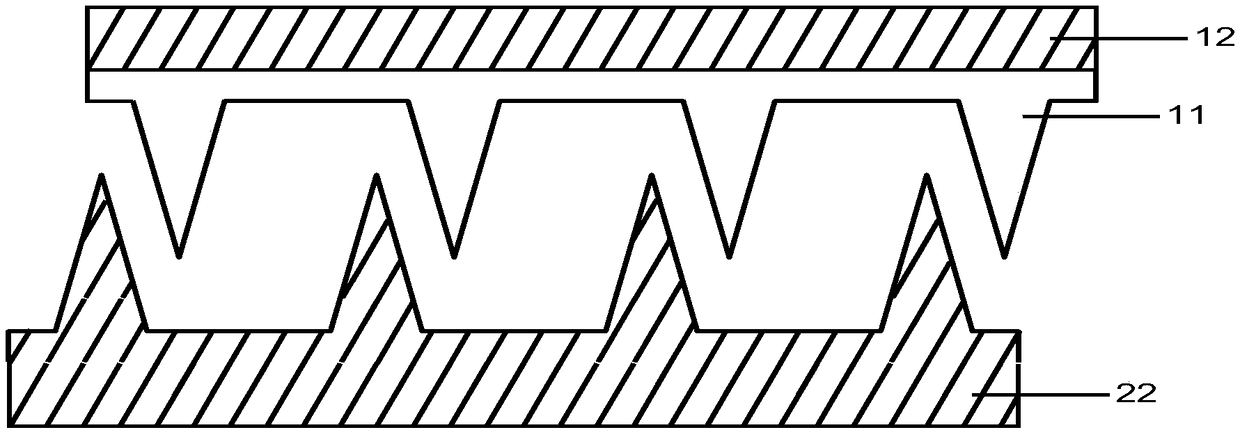
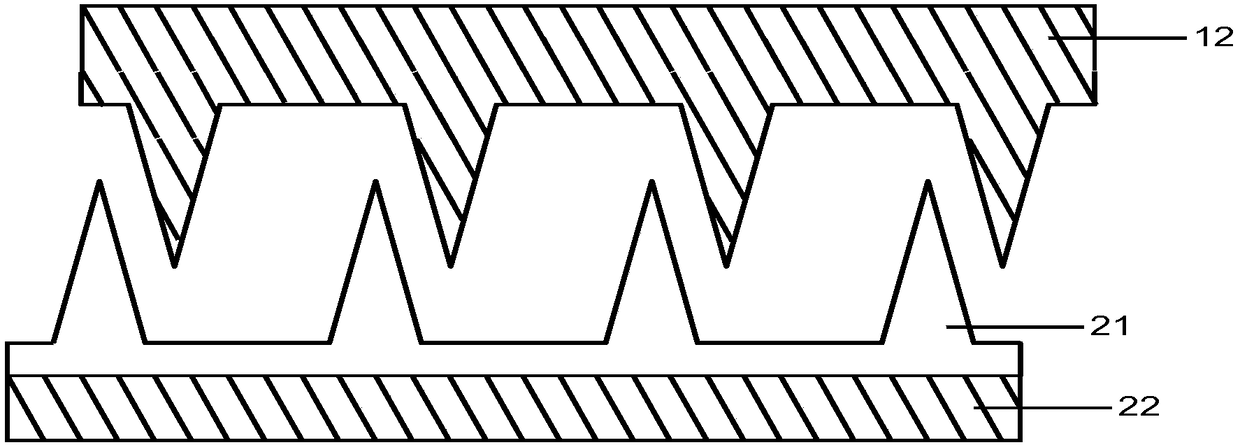
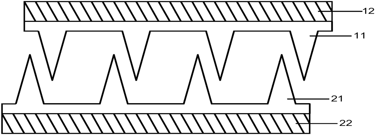
[0027] Figure 1(a)-Figure 1(c) A schematic structural diagram of a friction power generation device is provided for an embodiment of the present invention.

[0028] As shown in FIG. 1( a ), the friction power generation device may include: a first component and a second component that are oppositely arranged. The first component includes a first conductive layer 12 and a first friction layer 11, and the first friction layer 11 is arranged on the ...


PUM


Abstract

The embodiment of the invention provides a friction power generation device, which comprises a first part and a second part which are oppositely arranged, wherein the first part comprises a first conductive layer and a first friction layer; the second part comprises a second conductive layer and a second friction layer; at least one protruding structure on the lower surface of the first friction layer and at least one protruding structure on the upper surface of the second conductive layer are arranged in a cross manner; at least one protruding structure on the lower surface of the first conductive layer and at least one protruding structure on the upper surface of the second friction layer are arranged in a cross manner; and the electron gaining and losing capability of the material of the first friction layer is different from that of the second friction layer. The first part and the second part carry out relative motion under the action of external force, and the first part and thesecond part are repeatedly subjected to contact, friction and separation on the friction surface of the at least one protruding structure, wherein the friction surface is located on the side surface of the at least one protruding structure, so that inductive charges are formed on the first conductive layer and the second conductive layer.

Description

technical field [0001] The invention relates to the technical field of friction power generation, in particular to a friction power generation device. Background technique [0002] The triboelectric generator utilizes the different abilities of gaining and losing electrons of different materials, and realizes the output of electric power through charge transfer in the process of contact and separation. The key to friction generator technology is to achieve effective friction, which has the advantages of low cost and high output voltage, and has great application potential in the fields of textile fiber power generation, tidal power generation and electronic device power supply. However, with the development of microelectronics and microsystem technology, electronic devices and functional sensors are becoming more and more miniaturized, which limits the application area of ​​tribogenerators, and at the same time puts forward more requirements for the miniaturization and integ...

Claims


Application Information

Patent Timeline
Patent Type & Authority Applications(China)
IPC IPC(8): H02N1/04
CPCH02N1/04
Inventor 卜灵权胜江梁斌张景平桂美将陈张雄曾鑫
Owner CHINA UNIV OF GEOSCIENCES (BEIJING)
Why Eureka
Try Eureka