Communication method and device of stroboscopic information

A communication device and stroboscopic technology, which are applied in the field of communication, can solve the problems of inability to encrypt optical communication, and achieve the effect of improving security and encrypting information.

Active Publication Date: 2018-05-29
ZHONGKE RARE EARTH (CHANGCHUN) CO LTD
View PDF7 Cites 2 Cited by
  • Summary
  • Abstract
  • Description
  • Claims
  • Application Information

AI Technical Summary

Problems solved by technology

However, this patent still cannot effectively encrypt optical communication, in particular, it cannot divide optical communication into light with multiple changes at the same time for encrypted transmission

Method used


Image

  • Communication method and device of stroboscopic information
  • Communication method and device of stroboscopic information
  • Communication method and device of stroboscopic information

Examples


Embodiment 1

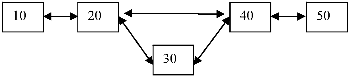
[0036] Such as figure 1 Shown is a schematic diagram of logic modules of the communication device of the present invention.

[0037] The invention provides a stroboscopic information communication device, which at least includes an optical signal transceiving unit, an optical signal processing unit and an optical communication network. Preferably, the communication device of the present invention includes a first communication device for sending optical signals, an optical communication network, and a second communication device for receiving optical signals. Preferably, the positions and purposes of the first communication device and the second communication device are interchangeable.

[0038] Such as figure 1 As shown, the first communication device includes a first optical signal processing unit 10 and a first optical signal transceiving unit 20 . The second communication device includes a second optical signal transceiving unit 40 and a second optical signal processing...

Embodiment 2

[0058] This embodiment is a further improvement on Embodiment 1, and repeated content will not be repeated here.

[0059] This embodiment provides a communication method for stroboscopic information, and the method includes the following steps:

[0060] Dividing the lighting cycle into at least two lighting phases in which the light is varied according to at least two characteristic curves, wherein the characteristic curve of at least one lighting phase changes in a manner approaching zero candela;

[0061] Safety verification is performed based on the characteristic curve of the first light-emitting stage in the light-emitting period, and the transmission information is acquired in a preset information conversion mode based on the characteristic curve of the second light-emitting stage when the safety verification is passed.

[0062] Preferably, the present invention also provides a communication method for stroboscopic information, the method includes the following steps:

...

Embodiment 3

[0074] This embodiment is a further improvement on Embodiment 1 and Embodiment 2 and their combination, and the repeated content will not be repeated.

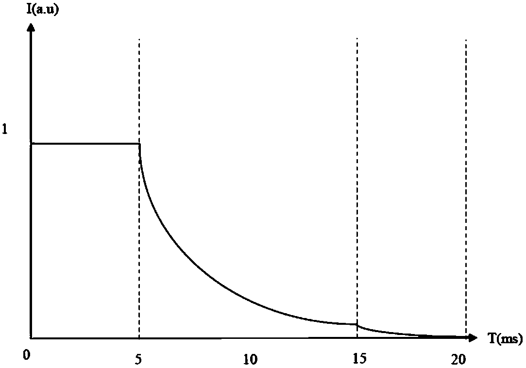
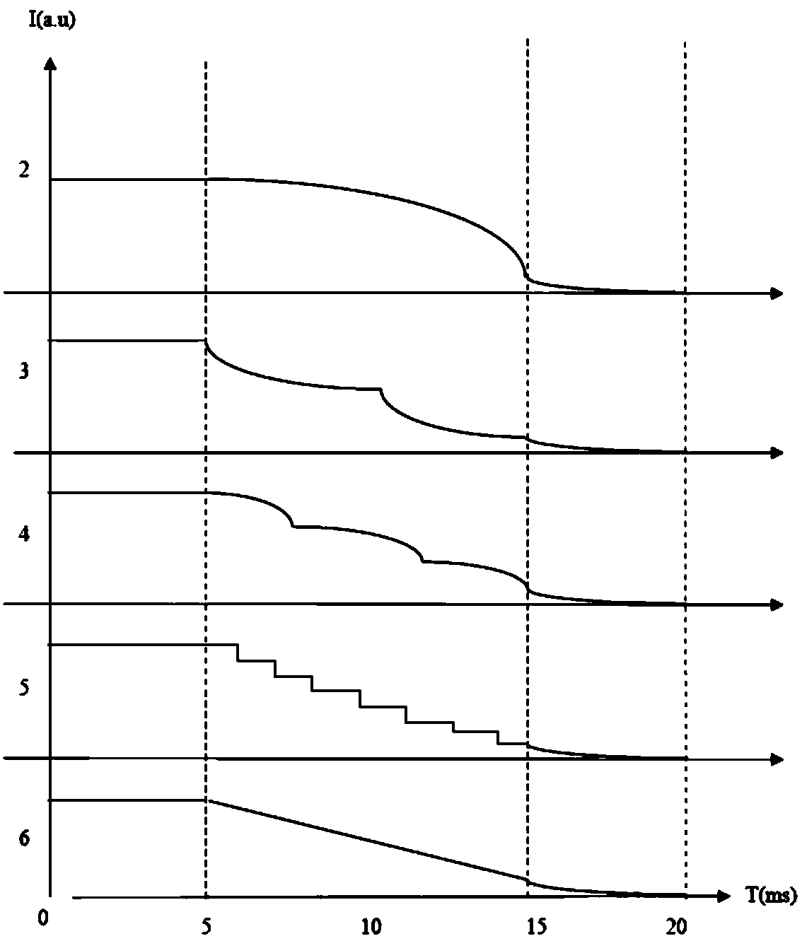
[0075] This example is for Figure 2 to Figure 10 The characteristic curve change of the optical signal is described in detail. The variation trend of the characteristic curve of the preferred first light-emitting stage of the present invention is as follows Figure 2 to Figure 4 shown. The horizontal axis in the figure represents time, and the unit is ms. The vertical axis represents intensity or relative intensity, and the unit is not limited, expressed by the international general symbol a.u. The light-emitting period of this embodiment is preferably 20ms, the first light-emitting period is 0-5ms, the second light-emitting period is 5-15ms, and the third light-emitting period is 15-20ms.

[0076] Such as figure 2 with image 3 In the luminescence curves No. 1-6 shown, the luminous intensity in the first luminescent s...


PUM


Abstract

The invention relates to a communication device of stroboscopic information. The communication device at least comprises an optical signal transmitting-receiving unit, an optical signal processing unit and an optical communication network; the first optical signal processing unit divides a light emission period into at least two light emission stages of light change according to at least two feature curves, wherein the feature curve of at least one light emission stage changes via a mode of being level off to zero candela; the first optical signal transmitting-receiving unit transmits an optical signal which carries preset information directly or through the optical communication network based on the stagewise curves of the light emission period sent by the optical signal processing unit;and the second optical signal processing unit performs safety verification based on the feature curve of the first light emission stage in the light emission period, which is received by the second optical signal transmitting-receiving unit, and obtains transmission information via a preset information conversion mode based on the feature curve of the second light emission stage when the safety verification passes. Encryption is carried out through optical parameters in multiple dimensions at different stages of the light emission period, and the degree of safety is relatively high.

Description

technical field [0001] The invention relates to the communication field, in particular to a communication method and a communication device for stroboscopic information. Background technique [0002] The security measures of the existing optical communication system still adopt stream cipher encryption and decryption technology based on electrical signal processing. Due to the limitation of electronic "bottleneck", the encryption and decryption rate is low, and the maximum rate in the laboratory is only 2.5Gbit / s . When an emergency occurs, the business volume of the existing optical communication network may increase by dozens or even hundreds of times. The traditional encryption and decryption technology based on electrical signal processing is difficult It is fully compatible with the next-generation all-optical communication network, and the rate of encryption and decryption technology based on all-optical signal processing can exceed 100Gbit / s. At the same time, the e...

Claims


Application Information

Patent Timeline
Patent Type & Authority Applications(China)
IPC IPC(8): H04B10/116H04B10/40H04L9/08H04L9/30H04B10/079
CPCH04B10/079H04B10/116H04B10/40H04L9/0863H04L9/3066
Inventor 李成宇张洪杰王森
Owner ZHONGKE RARE EARTH (CHANGCHUN) CO LTD
Why Eureka
Try Eureka