
Workpiece alignment method

A workpiece, multi-axis machining technology, used in metal processing machinery parts, metal processing, manufacturing tools and other directions, can solve the problem of time-consuming, labor-intensive and low accuracy in aligning the zero point of the workpiece angle, and achieves low time cost and high accuracy. , the effect of simple operation

Active Publication Date: 2018-06-01
WUHAN MARINE MACHINERY PLANT
View PDF9 Cites 5 Cited by
  • Summary
  • Abstract
  • Description
  • Claims
  • Application Information

AI Technical Summary

Problems solved by technology

[0004] In order to solve the time-consuming and labor-intensive and low-accuracy problem of aligning the zero point of the workpiece angle in the prior art, the embodiment of the present invention provides a method for aligning the workpiece

Method used


Image

  • Workpiece alignment method
  • Workpiece alignment method
  • Workpiece alignment method

Examples


Embodiment Construction

[0039] In order to make the object, technical solution and advantages of the present invention clearer, the implementation manner of the present invention will be further described in detail below in conjunction with the accompanying drawings.

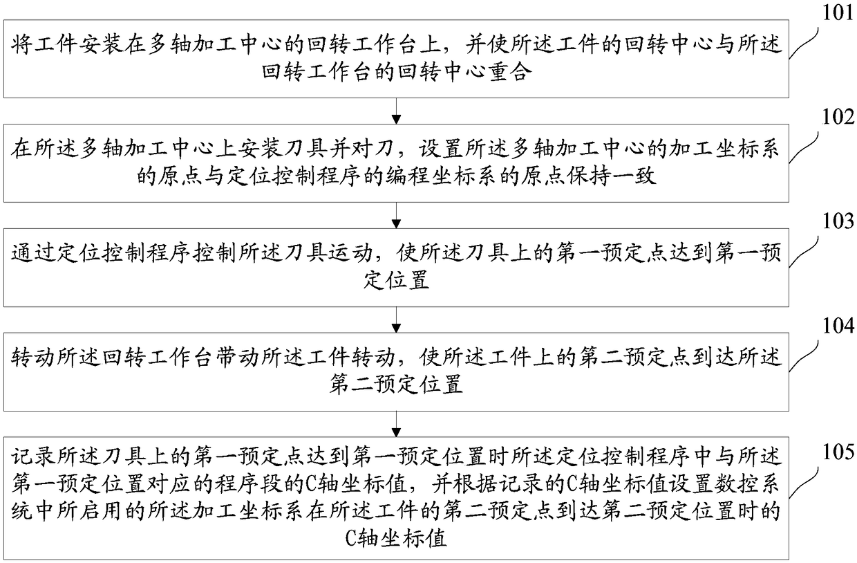
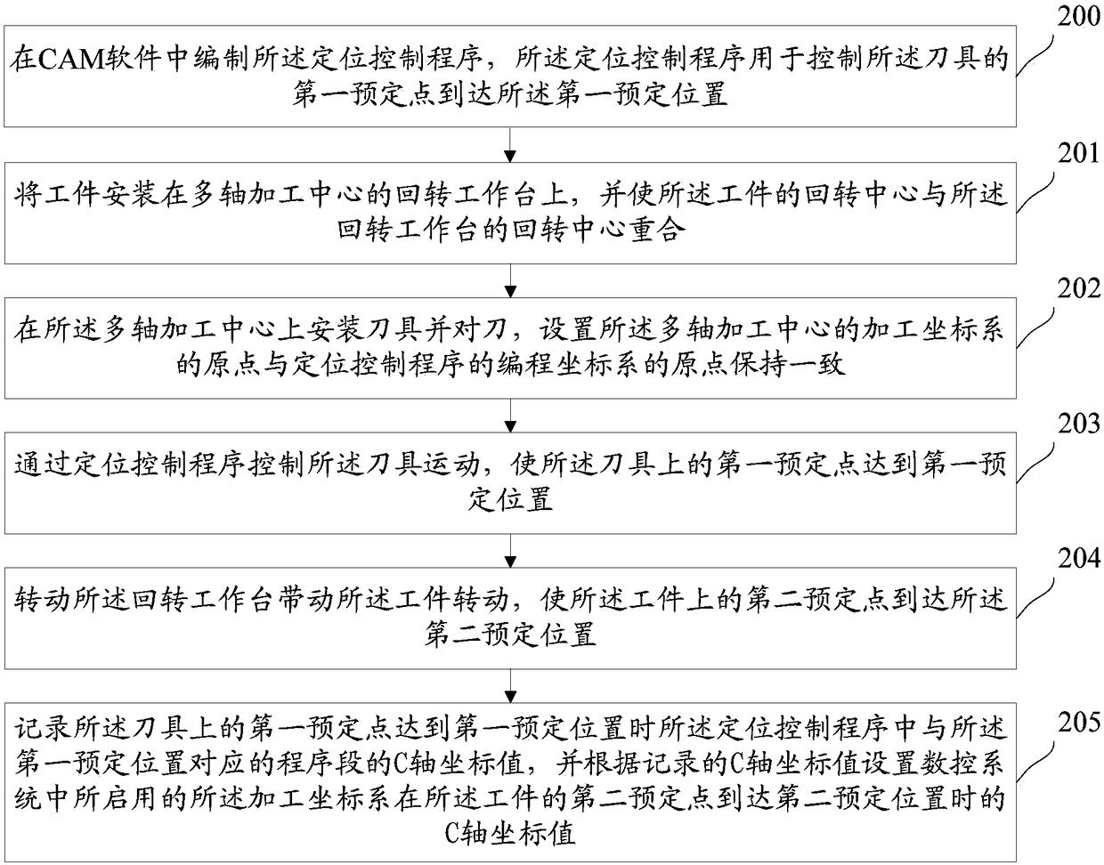
[0040] figure 1 It is a flow chart of a workpiece alignment method provided by an embodiment of the present invention, such as figure 1 As shown, the method includes:

[0041] Step 101: Install the workpiece on the rotary table of the multi-axis machining center, and make the rotary center of the workpiece coincide with that of the rotary table.

[0042] Among them, the center of rotation of the workpiece is also the central axis of the workpiece. It is installed on the center of rotation of the rotary table, and is aligned through subsequent steps, so that the multi-axis machining center can automatically control the tool for processing.

[0043] Step 102: install a tool on the multi-axis machining center and set the tool, set the o...


PUM


Abstract

The invention discloses a workpiece alignment method, and belongs to the technical field of machining. The method comprises the steps that a workpiece is installed on a rotary workbench of a multi-shaft machining center, and the rotation center of the workpiece is enabled to coincide with the rotation center of the rotary workbench; a cutter is installed on the multi-shaft machining center, cutteraligning is carried out, an original point of a processing coordinate system is set to be kept consistent with an original point of a programming coordinate system of a positioning control program, and the original point of the machining coordinate system is located on the rotation center of the workpiece; the positioning control program controls the cutter to move so as to make a first preset point on the cutter reach a first preset position; the rotary workbench is rotated to drive the workpiece to rotate so as to make a second preset point of the workpiece reach a second preset position, wherein the second preset position is a preset position corresponding to the first preset position; and C-axis coordinate values of the corresponding program segments in the positioning control programare recorded, and a C-axis coordinate value of a coordinate system started in a numerical control system is set according to the recorded C-axis coordinate values.

Description

technical field [0001] The invention relates to the technical field of mechanical processing, in particular to a workpiece alignment method. Background technique [0002] Machining of impellers is usually carried out on multi-axis machining centers. Generally, when a workpiece is processed by a multi-axis machining center, the origin of the machining coordinate system is usually set at a certain point on the centerline of the workpiece’s rotation, and an angular reference (such as diameter After the workpiece is installed, the angle zero point of the impeller can be corrected by correcting the angle reference, so that the angle and orientation of the workpiece installation are consistent with the angle and orientation of the three-dimensional model of the workpiece in the CAM (Computer Aided Manufacturing, computer-aided manufacturing) software . [0003] However, when finishing some impellers on a multi-axis machining center, the impellers do not have an angular reference...

Claims


Application Information

Patent Timeline
Patent Type & Authority Applications(China)
IPC IPC(8): B23Q15/22
CPCB23Q15/22
Inventor 付跃飞杨家军唐长平杜文国程哲刘伟刘燕翎
Owner WUHAN MARINE MACHINERY PLANT
Learn More