
Electric double oil pump system for steering and braking of sanitation vehicle

A technology that uses electric dual- and sanitation vehicles. It is applied in the direction of brake transmission, brakes, and steering mechanisms. It can solve the problems of easy overloading of hydraulic pumps, failure to brake, and high noise of electric pumps.

Pending Publication Date: 2018-06-01
ZHENGZHOU YUTONG HEAVY IND
View PDF0 Cites 0 Cited by
  • Summary
  • Abstract
  • Description
  • Claims
  • Application Information

AI Technical Summary

Problems solved by technology

The power steering system of the 7T sanitation vehicle adopts an electro-hydraulic power assist system. If the brake power assist system adopts a vacuum hydraulic power boost system, there may be a risk of not being able to brake due to the heavy load of the whole vehicle. Dynamic load requirements, but the curb weight of the whole vehicle has increased by about 1T, and the sanitation vehicle has no suitable position for electric air compressors, gas cylinders and other related components due to the layout of the upper body system and the tank body at the rear
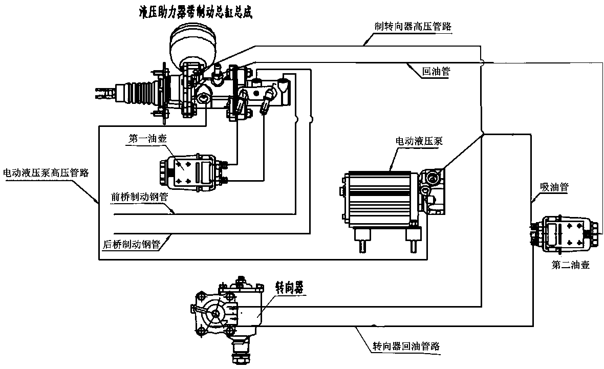
The current mainstream solution is to use the electric pump with a single hydraulic pump as the common power source for steering and braking. The disadvantage of this solution is that the hydraulic pump is easily overloaded, and the vibration of the high-pressure pipeline causes the electric pump to work loudly. The principle is as follows: figure 1 shown

Method used


Image

  • Electric double oil pump system for steering and braking of sanitation vehicle
  • Electric double oil pump system for steering and braking of sanitation vehicle
  • Electric double oil pump system for steering and braking of sanitation vehicle

Examples


Embodiment Construction

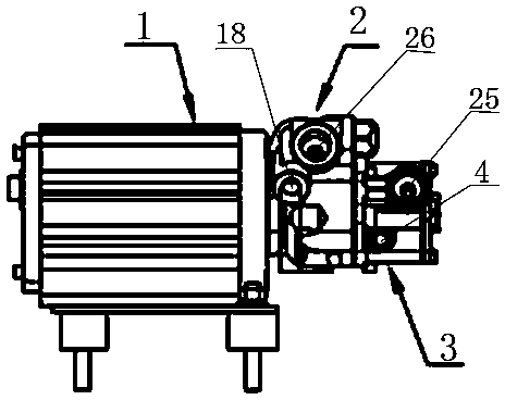
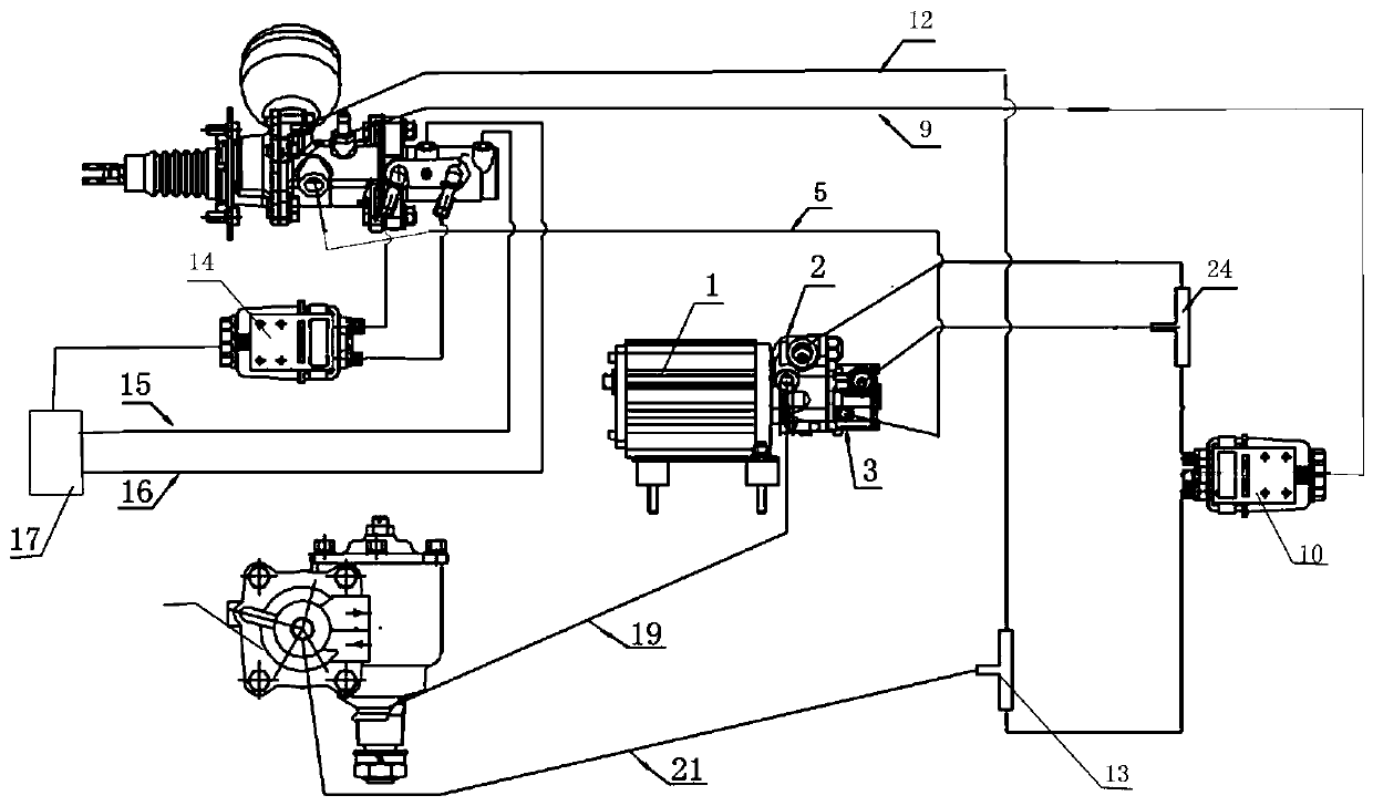
[0018] as attached Figure 2-5 As shown, an electric dual oil pump system for steering and braking of a sanitation vehicle includes a motor 1, the motor 1 is connected with a steering hydraulic pump 2 through a coupling, and the brake hydraulic pump 3 is arranged outside the steering hydraulic pump 2. The steering hydraulic pump The rotor of 2 is coaxial with the rotor of the brake hydraulic pump 3. The hydraulic booster with brake master cylinder assembly 6 includes the hydraulic booster 7 and the brake master cylinder 8. The brake hydraulic pump oil outlet 4 passes through the brake hydraulic pump oil outlet pipe 5 It communicates with the oil inlet 701 of the hydraulic booster, the first oil return port 702 of the hydraulic booster communicates with the first oil inlet 11 of the second oil pot 10 through the first oil return pipe 9, and the second oil return port 703 of the hydraulic booster passes through The second oil return pipe 12 is communicated with the oil inlet of ...


PUM


Abstract

The invention discloses an electric double oil pump system for steering and braking of a sanitation vehicle. A motor is connected with a steering hydraulic pump through a coupling, a braking hydraulicpump is arranged on the outer side of the steering hydraulic pump, a rotor of the steering hydraulic pump is co-axial with a rotor of the braking hydraulic pump, an oil outlet of the braking hydraulic pump is communicated with an oil inlet of a hydraulic booster, and a first oil returning port of the hydraulic booster is communicated with a first oil inlet of a second oil pot; a low-pressure oilinlet of a braking master cylinder is communicated with an oil outlet of a first oil pot, and a high-pressure oil outlet of the braking mater cylinder is communicated with an oil inlet of the hydraulic braking system; an oil outlet of the steering hydraulic pump is communicated with a steering device, and the steering device is communicated with a first three-way valve; the first three-way valve is communicated with a second oil inlet of the second oil pot, and a second three-way valve is communicated with an oil inlet of the braking hydraulic pump and an oil inlet of the steering hydraulic pump respectively. The system aims at solving the problem of boosting source of a hydraulic braking system of a 7T sanitation vehicle, and reduces noises generated by the hydraulic system when a steering wheel is steered and a braking pedal is pressed.

Description

technical field [0001] The invention belongs to the technical field of hydraulic auxiliary braking, and in particular relates to an electric double oil pump system for steering and braking of a sanitation vehicle, which is used to solve the problem that a 7T medium-sized pure electric sanitation vehicle adopts a hydraulic braking system power source. The complete set of air brake system components can also achieve vehicle weight reduction and noise reduction. Background technique [0002] At present, the power steering system of pure electric sanitation vehicles generally adopts electric power steering system (EPS) and electro-hydraulic power steering system (EHPS). The electric power steering system uses a low-voltage (24V) low-power booster motor, which provides less assist, so it is generally used for small vehicles with a small front axle load. The electro-hydraulic power steering system uses a high-pressure electric steering oil pump to provide the steering gear with a...

Claims


Application Information

Patent Timeline
Patent Type & Authority Applications(China)
IPC IPC(8): B60T13/14B62D5/06
CPCB60T13/145B60T13/146B62D5/062B62D5/064
Inventor 李永旺赵玉东张垒成宗源
Owner ZHENGZHOU YUTONG HEAVY IND
Learn More