Crane

A crane and reel technology, applied in the direction of the spring mechanism and the hoisting device, can solve the problems of wire rope wear, trouble, and difficult to clean, and achieve the effect of saving lubricating oil and facilitating lubrication.

Active Publication Date: 2018-06-01
徐州天骋智能科技有限公司
View PDF5 Cites 0 Cited by
  • Summary
  • Abstract
  • Description
  • Claims
  • Application Information

AI Technical Summary

Problems solved by technology

[0005] The existing technology has the following technical problems: 1. The general method of steel wire rope lubrication is to directly apply grease on the steel wire rope manually, which is very troublesome; 2. Af

Method used


Image

  • Crane
  • Crane
  • Crane

Examples


Embodiment 1

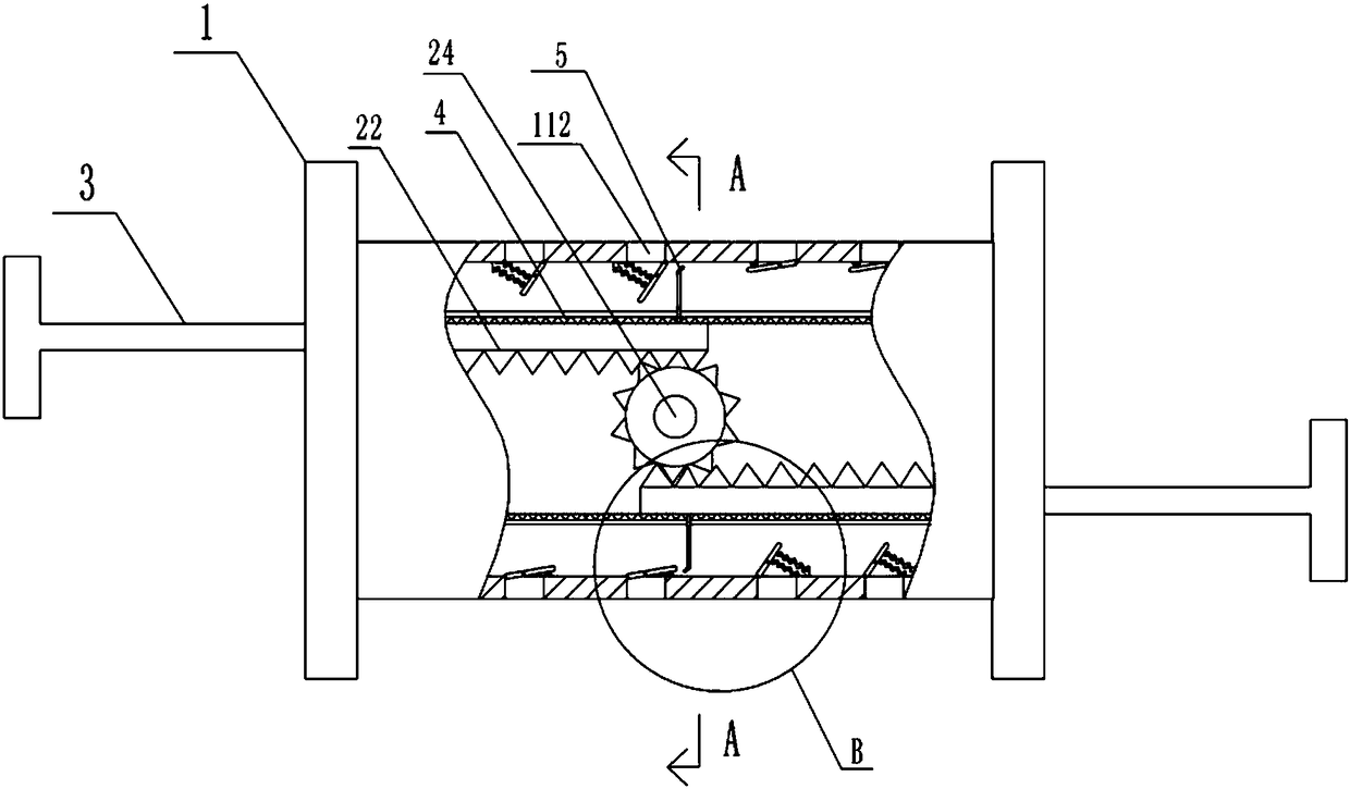
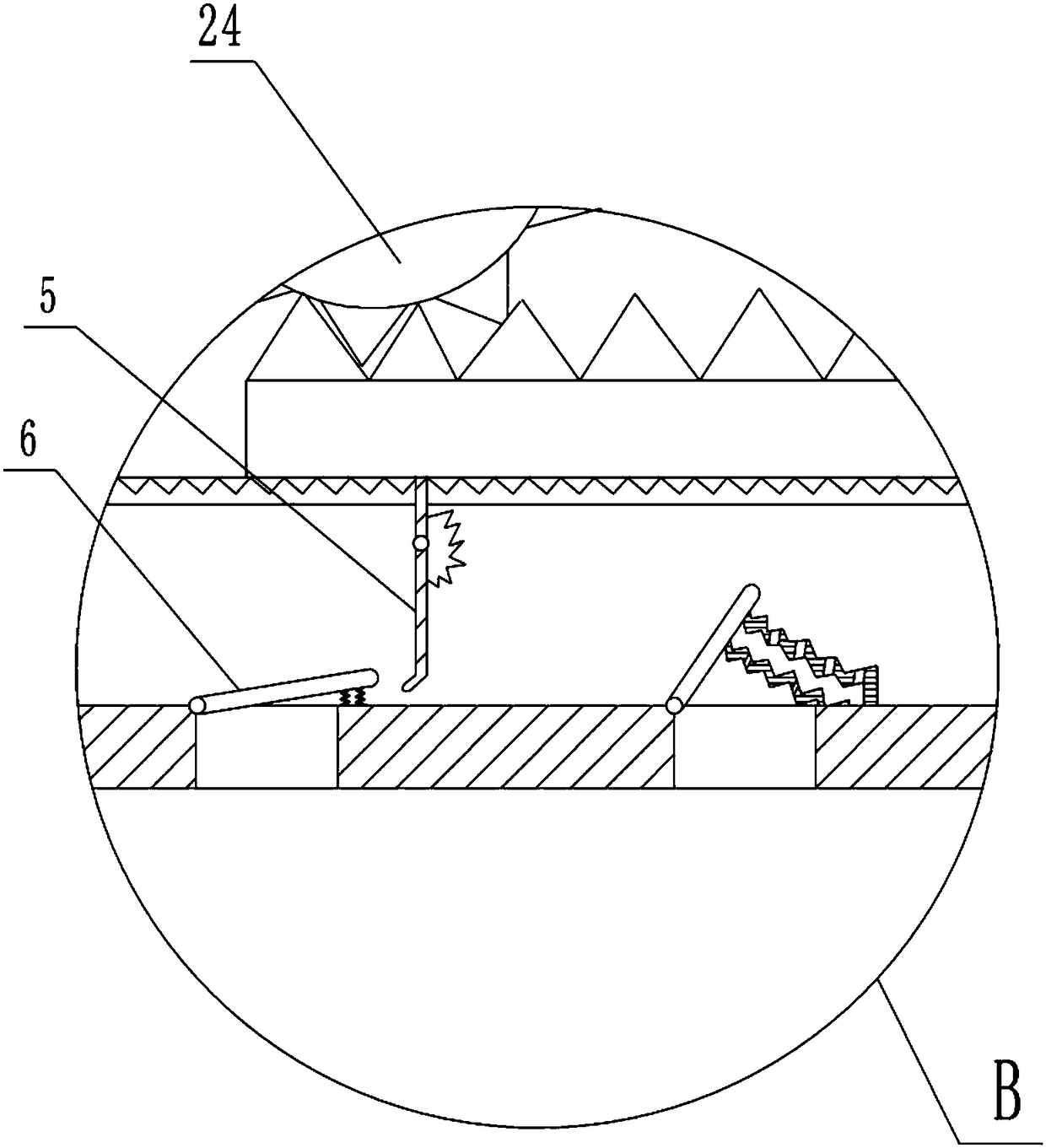
[0030] Such as figure 1 , figure 2 , image 3 with Figure 5 Shown, in order to achieve the above object, basic scheme of the present invention is as follows:

[0031]A kind of crane, comprises reel body 1, and reel body 1 is provided with cavity inside, and outer sleeve 111 is arranged in the cavity, and the two ends of outer sleeve 111 are fixedly connected with the chamber wall of cavity; An oil chamber 12 for containing lubricating oil is formed between 111 and the wall of the cavity. The reel body 1 is provided with an oil inlet portion for feeding the oil chamber 12, and the oil inlet portion is an oil inlet hole with a cover. The outer sleeve 111 is provided with an inner sleeve 2 and a push rod 3, and the inner sleeve 2 is slidingly connected with the inner wall of the outer sleeve 111; one end of the push rod 3 is fixed to the inner sleeve 2, and the other end of the push rod 3 protrudes to the outside of the reel body 1, and the push rod 3 is slidably connected ...

Embodiment 2

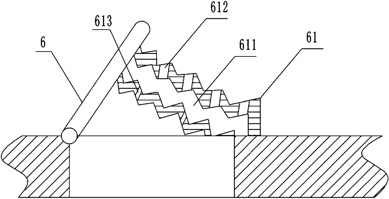
[0040] The difference between this embodiment and Embodiment 1 is that, in order to further enable the swing bar 52 to return to its original position, the cover plate 6 can better squeeze the soft folding layer 61, such as Image 6 As shown, the cover plate 6 is provided with an opening, and a shaft 62 is rotatably connected to the opening, and a pressing plate 63 is fixed on the shaft 62 . A block 64 for preventing the pressing plate 63 from turning upward is also fixed on the upper surface of the cover plate 6 . Such as Image 6 The left side of the blocking block 64 shown is bent downward and fixedly connected with the cover plate 6 ; the right side of the blocking block 64 is bent downward and contacts the upper surface of the pressing plate 63 .

[0041] After the cover plate 6 is fully opened, pull the push rod 3 on the left side, and the left side push rod 3 drives the left side for the shape sleeve to move to the left, and the swing rod at the lower end of the toggle...


PUM


Abstract

The invention relates to the technical field of the structure of loading suspension elements, in particular to a crane. The crane comprises a coiling block body. The coiling block body is internally provided with a cavity. An outer sleeve is arranged in the cavity. The two ends of the outer sleeve are fixedly connected with the cavity wall of the cavity. An oil cavity is formed between the outer sleeve and the cavity wall of the cavity. The coiling block body is provided with an oil inlet part. An inner sleeve and a push rod are arranged in the outer sleeve. One end of the push rod is fixed tothe inner sleeve. The other end of the push rod extends out of the coiling block body. The push rod is slidably connected with the coiling block body. The sleeve wall of the outer sleeve is providedwith strip-shaped slots. An elastic folding layer is arranged in the strip-shaped slots. Shifting bars penetrating through the elastic folding layer are fixed to the outer wall of the inner sleeve. The cavity wall of the cavity is provided with oil outlet holes. Cover plates are arranged at the oil outlet holes. A soft folding layer is fixed to the side, close to each oil outlet hole, of the corresponding cover plate. Through the crane, a steel wire rope can be lubricated conveniently, and solid impurities such as gravels can be cleaned.

Description

technical field [0001] The invention relates to the structural technical field of load hanging components, in particular to a crane. Background technique [0002] A crane refers to a multi-action hoisting machine that lifts vertically and carries heavy objects horizontally within a certain range. Also known as crane, aerial crane, crane. Regular lubrication should be carried out on the parts where the crane has shafts and holes and the mechanical parts with relative motion friction surfaces; and all kinds of cranes are like this. Due to the different working conditions, the requirements for the lubrication point of the device are also different. For various types of cranes and lubricating points in different parts, it is necessary to carry out periodic maintenance and regular inspection according to the regulations of their manuals, and use qualified grease to lubricate them, so as to make the machine run normally and overcome early wear and tear. [0003] Among them, the...

Claims


Application Information

Patent Timeline
IPC IPC(8): B66D1/28
CPCB66D1/28
Inventor 寇瑞东
Owner 徐州天骋智能科技有限公司
Why Eureka
Try Eureka