
A variable compression ratio engine mechanism

A technology of compression ratio and engine, which is applied in the direction of engine control, machine/engine, mechanical equipment, etc., can solve the problems of complex variable compression ratio mechanism system, incompatible engine size reduction, compression ratio can not be adjusted, etc., to achieve simple structure, The effect of fast adjustment speed and low possibility of failure

Active Publication Date: 2020-04-07
DONGFENG MOTOR CORP HUBEI
View PDF18 Cites 2 Cited by
  • Summary
  • Abstract
  • Description
  • Claims
  • Application Information

AI Technical Summary

Problems solved by technology

[0004] It should be noted that the variable compression ratio mechanism system is complicated, and the control piston, control tooth plate, combustion tooth plate, etc. are newly designed compared with the traditional engine. The hydraulic system needs high-pressure oil to maintain the pressure to control the change of the compression ratio. The control system is complicated. Due to the failure of the control system, the risk of the compression ratio being unable to be adjusted is very high; due to the increase of the control piston, etc., the cylinder, cylinder The width of the cover, etc. is increased, which is not conducive to the arrangement of parts in the cabin, and does not conform to the trend of reducing the size of the engine

Method used


Image

  • A variable compression ratio engine mechanism
  • A variable compression ratio engine mechanism
  • A variable compression ratio engine mechanism

Examples


Embodiment Construction

[0026] The present invention will be further described in detail below in conjunction with the accompanying drawings and specific embodiments.

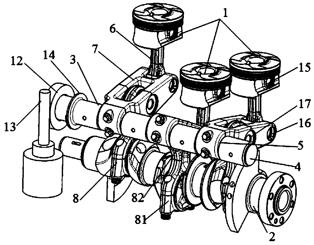
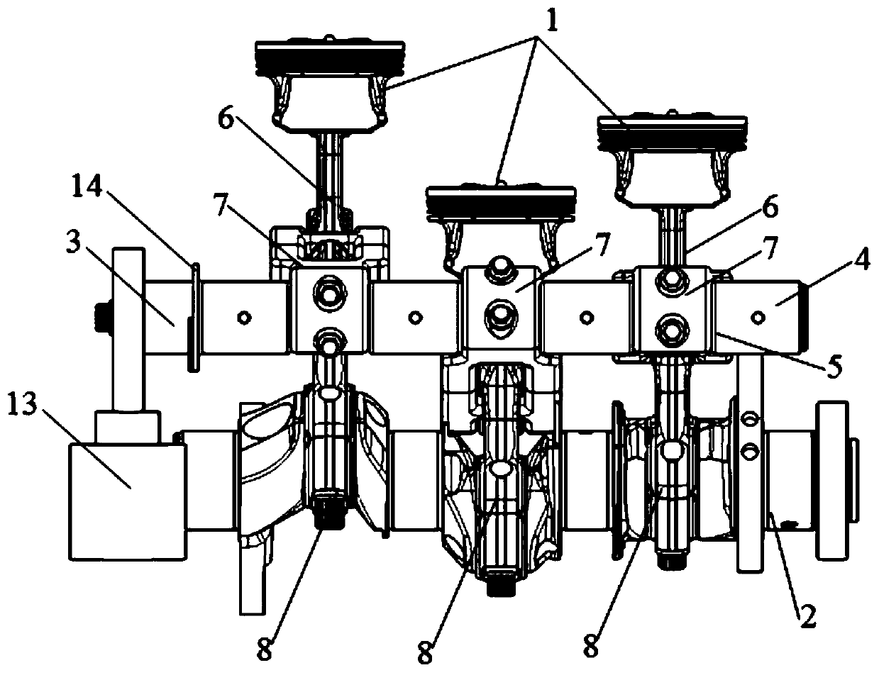
[0027] Such as Figure 1-2 As shown, a variable compression ratio engine mechanism provided by the present invention includes a crankshaft 2 axially connected to the cylinder block (not shown in the figure) and each piston 1 linked above, and also includes a crankshaft 2 and a piston. 1 eccentric shaft 3, the eccentric shaft 3 includes a main shaft body 4 and an auxiliary shaft body 5 eccentrically arranged on the main shaft body 4, the diameter of the auxiliary shaft body 5 is smaller than the main shaft body 4, and the end of the main shaft body 4 is axially connected with the cylinder body and There is a drive mechanism for driving the main shaft body 4 to rotate, and each piston 1 is connected with the eccentric shaft countershaft body 5 and the crankshaft 2 through a multi-stage connecting rod device that can change the total len...


PUM


Abstract

The invention discloses a novel engine mechanism with the variable compression ratio. The novel engine mechanism with the variable compression ratio is characterized by comprising a crank shaft whichis axially connected with a cylinder body and pistons which are on the crank shaft and in linkage with the crank shaft, and further comprising an eccentric shaft arranged between the crank shaft and the pistons, wherein the eccentric shaft comprises a main shaft body and auxiliary shaft bodies which are eccentrically arranged on the main shaft body, the end part of the main shaft body is axially connected with the cylinder body and is provided with a driving mechanism for driving the main shaft body to rotate; and the pistons are connected with the auxiliary shaft bodies of the eccentric shaftand the crank shaft through multi-stage connecting rod devices which are capable of changing the total length of connecting rods when the main shaft body rotates. According to the novel engine mechanism with the variable compression ratio, the structure is simple, the eccentric shaft is driven to rotate to move the positions of stop points on the pistons by controlling a motor, and therefore thevolume and the compression ratio of a combustion chamber can be changed, and the compression ratio can be changed; and the mechanism with the variable compression ratio belongs to mechanical movementcomponents, and therefore the possibility of fault is small, and the reliability is high.

Description

technical field [0001] The invention relates to an automobile engine, in particular to a gasoline engine applied to a passenger vehicle, specifically to an engine mechanism with a variable compression ratio. Background technique [0002] From the published invention patent CN101375039A, it can be seen that a cylinder head and engine block assembly for a variable compression ratio engine includes a combustion piston, a combustion tooth plate, a swing rod gear, a control tooth plate, a control piston, a hydraulic actuator, etc. Components; the crankshaft is connected with the swing rod gear through the connecting rod; the movement principle of the system is that when the control piston does not move, with the rotation of the crankshaft, the connecting rod and the control tooth plate are driven, and the control tooth plate is used as the fulcrum to drive the combustion gear. The plate and the combustion piston move up and down to realize the normal operation of the engine at a ...

Claims


Application Information

Patent Timeline
Patent Type & Authority Patents(China)
IPC IPC(8): F02D15/04F02B75/04
CPCF02B75/04F02D15/04
Inventor 蔡文新宋扬王文建邹伟桂强
Owner DONGFENG MOTOR CORP HUBEI
Learn More