Power rotation-angle output case capable of achieving positive and negative rotation

A forward and reverse, output box technology, applied in the direction of transmission components, transmission devices, transportation and packaging, etc., can solve the problems of many forward gears, unfavorable overall layout, high manufacturing cost, etc., to achieve front and rear double power output, easy to be independent Shifting operation, the effect of meeting the needs of multi-purpose

Pending Publication Date: 2018-06-01
GUANGXI LANGUANG TECH
View PDF10 Cites 2 Cited by
  • Summary
  • Abstract
  • Description
  • Claims
  • Application Information

AI Technical Summary

Problems solved by technology

[0002] At present, the forward and backward operations of the agricultural machinery used in China are generally through setting forward gears and reverse gears in the gearbox. There are many forward gears and few reverse gears. With the rapid development of agricultural mechanization, one machine with multiple functions It has become a development trend. Fine farming has higher and higher requirements for machines. However, in traditional gearboxes, there are many forward gears, few reverse gears, and a large speed ratio span, which cannot meet the requirements of multi-working conditions and multiple crops. Too few reverse gears It cannot meet the requirements of fine positioning and fast reverse when some machines are working, which greatly reduces the working efficiency
If multiple reverse gears are directly added to the gearbox with traditional structure, the structure is more complicated, the manufacturing cost is high, the volume is large, and the maintenance is difficult, which is not conducive to the overall layout

Method used


Image

  • Power rotation-angle output case capable of achieving positive and negative rotation
  • Power rotation-angle output case capable of achieving positive and negative rotation
  • Power rotation-angle output case capable of achieving positive and negative rotation

Examples


Embodiment Construction

[0017] The present invention will be further described below in conjunction with the accompanying drawings.

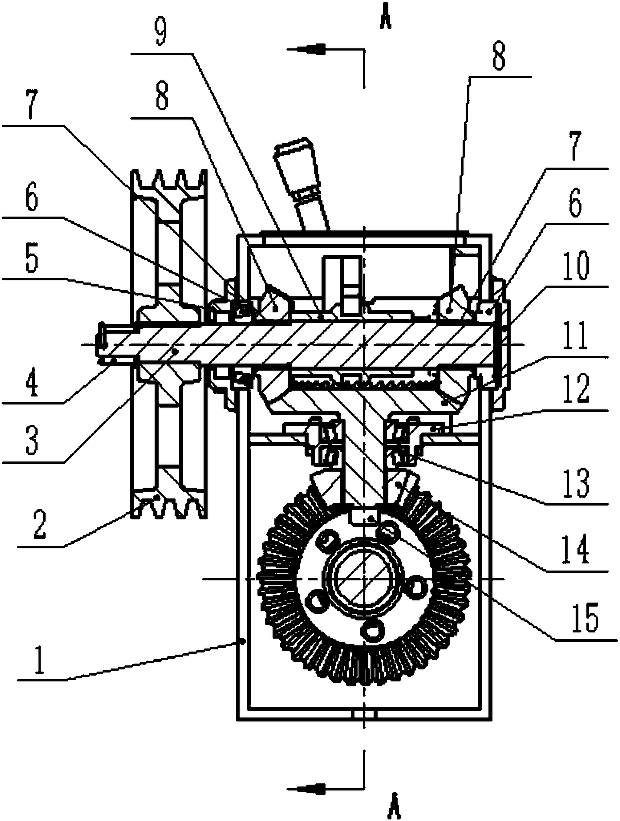
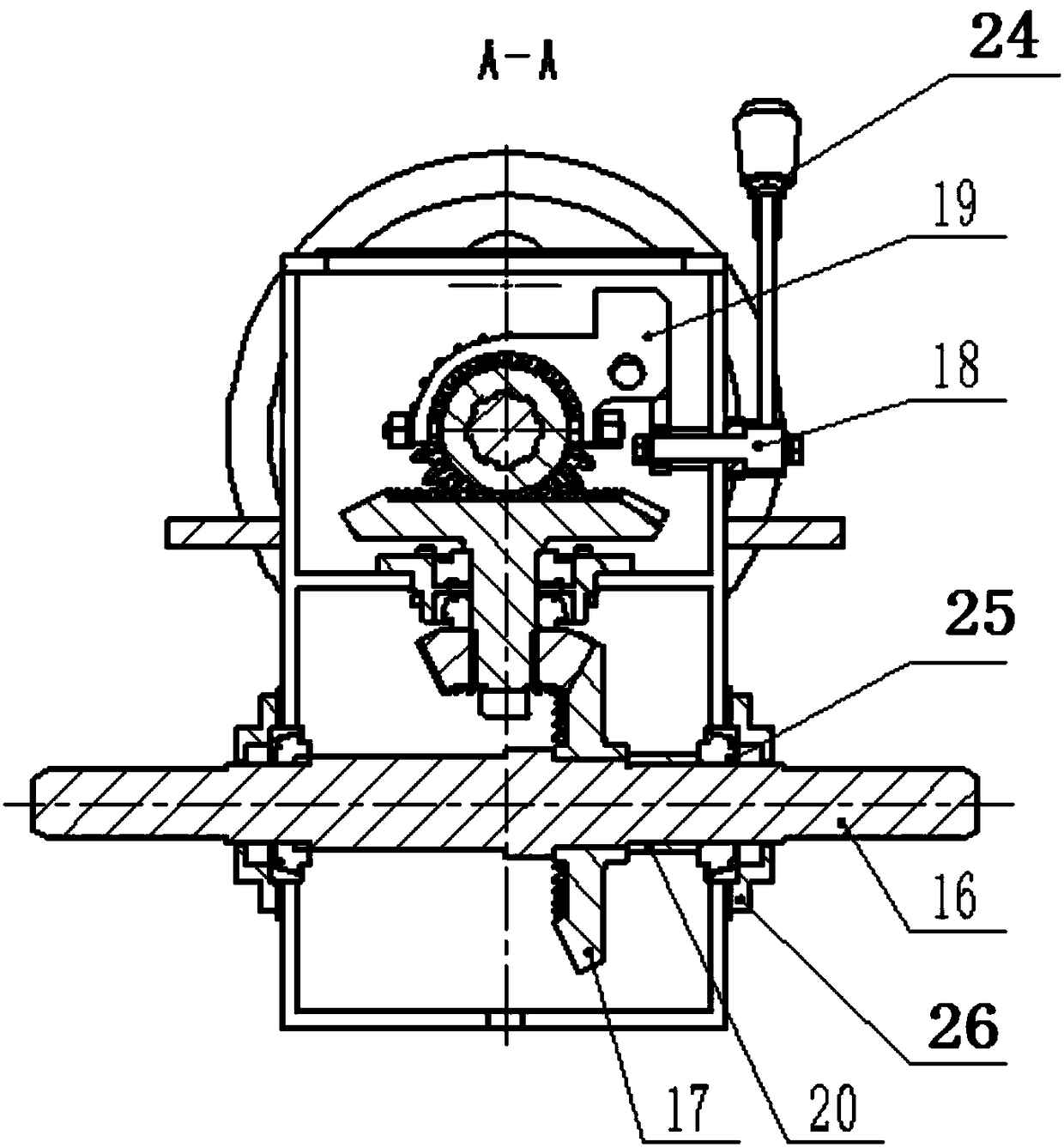
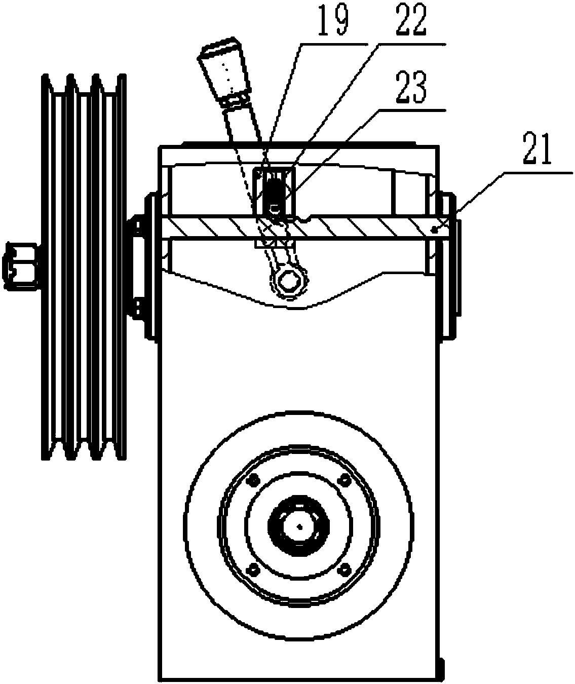
[0018] As shown in the drawings, the present invention realizes the forward and reverse power angle output box, which includes a box body 1 and a clutch 2. There are input shafts 3 and output shafts 16 arranged in a cross in the box body 1, and the input shaft 3 is on the top. , the output shaft 16 is below. The two ends of input shaft 3 are installed on the box body 1 by bearing one 6, and bearing cover one 5 is installed on the outside of bearing one 6 on the left side, and bearing cover two 10 is installed on the outside of bearing one 6 on the right side; End is installed on the casing 1 by bearing three 25 respectively, and the outside of bearing three 25 is equipped with bearing cover three 26. In the inner cavity of the box body 1, the middle part of the input shaft 3 is connected with a shift sliding sleeve 9 that can move left and right through a spline, and ...


PUM


Abstract

The invention discloses a power rotation-angle output case capable of achieving positive and negative rotation. The power rotation-angle output case comprises an input shaft and an output shaft, wherein the input shaft and the output shaft are arranged in a crossed manner. A gear-shifting sliding sleeve is mounted on the input shaft. Input shaft bevel gears are mounted at the two sides of the gear-shifting sliding sleeve through copper sleeves. A middle shaft large bevel gear and a middle shaft small bevel gear are mounted between the input shaft and the output shaft, wherein the middle shaftlarge bevel gear is coaxial with the middle shaft small bevel gear. The middle shaft large bevel gear is engaged with the input shaft bevel gears. The middle shaft small bevel gear is engaged with anoutput shaft bevel gear mounted on the output shaft. A gear shifting fork is arranged at the outer side of the gear-shifting sliding sleeve and mounted on a shifting fork connecting rod in a sleevingmanner. The shifting fork connecting rod is provided with three grooves. The gear shifting fork is provided with a clamping pin and a compression spring, wherein the clamping pin can be clamped into the grooves, and the compression spring jacks the clamping pin in a pressing manner. The gear shifting fork is shifted by a gear-shifting mandrel assembly to move leftwards and rightwards. The gear-shifting mandrel assembly is connected with a gear-shifting handle. By means of the power rotation-angle output case, 90-degree power reversing, positive and negative rotation power steady output and forward and backward double-power output can be achieved; the power rotation-angle output case runs reliably; and the multi-purpose requirement can be met.

Description

technical field [0001] The invention relates to agricultural machinery equipment, in particular to a power corner output box which is applied to the running mechanisms of agricultural machinery such as 30-70 horsepower tractors and self-propelled rotary cultivators and can realize forward and reverse rotation. Background technique [0002] At present, the forward and backward operations of the agricultural machinery used in China are generally through setting forward gears and reverse gears in the gearbox. There are many forward gears and few reverse gears. With the rapid development of agricultural mechanization, one machine with multiple functions It has become a development trend. Fine farming has higher and higher requirements for machines. However, in traditional gearboxes, there are many forward gears, few reverse gears, and a large speed ratio span, which cannot meet the requirements of multi-working conditions and multiple crops. Too few reverse gears It cannot meet ...

Claims


Application Information

Patent Timeline
Patent Type & Authority Applications(China)
IPC IPC(8): F16H3/14F16H3/091F16H57/023
CPCF16H3/091F16H3/145F16H57/023F16H2003/0811F16H2200/2035
Inventor 巫硕琦白承晖庞莲香
Owner GUANGXI LANGUANG TECH
Why Eureka
Try Eureka