
Steel rail flatness and torsion detection device and method

A detection method and technology of detection equipment, which are applied to measurement devices, instruments, optical devices, etc., can solve problems such as the need to improve detection efficiency, sensor zero offset, and inaccurate measurement on one side, and achieve a wide working temperature range and high altitude. Accurate and improve the effect of detection accuracy

Inactive Publication Date: 2018-06-01
NANJING INST OF ADVANCED LASER TECH
View PDF9 Cites 3 Cited by
  • Summary
  • Abstract
  • Description
  • Claims
  • Application Information

AI Technical Summary

Problems solved by technology

This method places a laser displacement sensor on one side of the rail, but in actual detection, the linear motion mechanism will inevitably vibrate, which will drive the sensor to vibrate together, which will cause the problem of zero offset of the sensor, resulting in inaccurate measurement on one side. At the same time, this method also needs to stop the line detection, and the detection efficiency needs to be improved.

Method used


Image

  • Steel rail flatness and torsion detection device and method
  • Steel rail flatness and torsion detection device and method
  • Steel rail flatness and torsion detection device and method

Examples


Embodiment Construction

[0029] The technical solutions of the present invention will be further described below in conjunction with the accompanying drawings and embodiments.

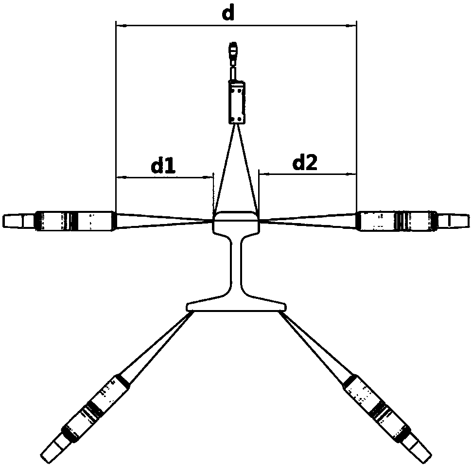
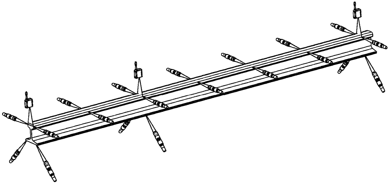
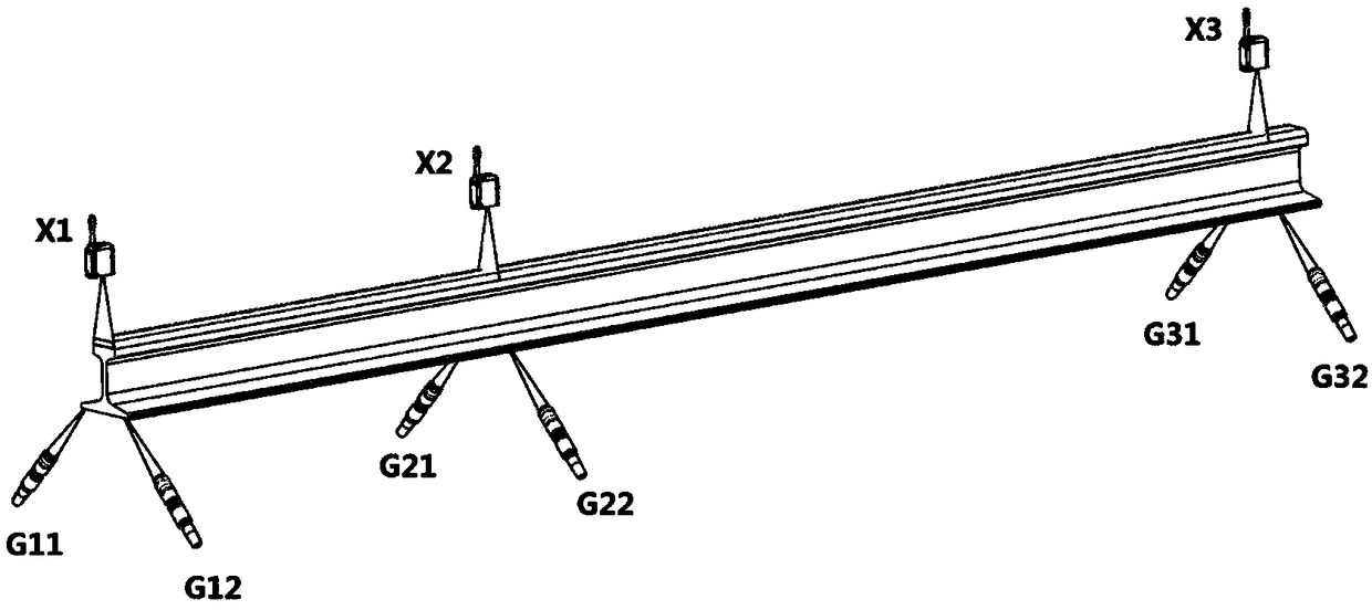
[0030] Such as figure 1 Shown is the rail straightness and torsion detection equipment according to the present invention, which includes a plurality of spectral confocal displacement sensors and a plurality of linear laser profile sensors. Multiple spectral confocal displacement sensors G are placed symmetrically on both sides of the rail head and the bottom of the rail to measure the distance from the measured point to the sensor on the side of the rail head and the bottom of the rail; multiple linear laser profile sensors X are placed on The top of the rail head to capture the rail tread curve. A plurality of spectral confocal displacement sensors and a plurality of linear laser profile sensors are connected with the data acquisition memory, so that the collected data are analyzed and processed to obtain the straightness a...


PUM


Abstract

The present invention discloses a steel rail flatness and torsion detection device and method. The device comprises a plurality of spectral confocal displacement sensors and a plurality of linear laser contour sensors. The spectral confocal displacement sensors are symmetrically arranged at two sides of a steel rail and two sides of the bottom portion of the steel rail to measure distances from the side of a rail head of the steel rail and measured points at the bottom portion of the steel rail to the sensors; the linear laser contour sensors are put at the top portion of the rail head of thesteel rail to collect a steel rail tread curve; and the spectral confocal displacement sensors and the linear laser contour sensors are connected with a data collection storage to perform analysis andprocessing to obtain the flatness and torsion of the steel rail. The detection method mainly employs the spectral confocal displacement sensors and the linear laser contour sensors to collect geometrical parameters of the surface of the steel rail to obtain flatness and torsion of the steel rail through data analysis and calculation.

Description

technical field [0001] The invention relates to the field of automatic detection of rails, in particular to a detection device and method for straightness and torsion of a rail. Background technique [0002] With the development of high-speed railways and passenger dedicated lines in China, the quality of long rails has attracted more and more attention. The straightness and twist of the rails are one of the important indicators to measure the quality of the rails, which directly affect the running speed and comfort of the train, and even endanger the driving safety in severe cases. The shape of the rails needs to be inspected before the rails are welded to avoid unqualified rails being put into production and causing unnecessary losses. Therefore, it is necessary to develop a high-precision rail straightness and twist detection system to meet the increasingly high requirements . [0003] Wang Wanghua and others used 16 laser ranging sensors of the same type to complete th...

Claims


Application Information

Patent Timeline
IPC IPC(8): G01B11/26G01B11/24
CPCG01B11/24G01B11/26
Inventor 曾爱军庆祖林张飞王刘靖张凯思
Owner NANJING INST OF ADVANCED LASER TECH
Learn More