Optical fiber fixture for observing and analyzing breaking point of optical fiber

A breaking point and optical fiber technology, applied in the field of tooling and fixtures, can solve the problems of unseen optical fiber optical fiber fixtures, etc., and achieve the effect of simple structure, small overall volume, and avoiding the breaking of optical fibers.

Pending Publication Date: 2018-06-01
QINGHAI ZHONGLI OPTICAL FIBER TECH CO LTD
View PDF2 Cites 2 Cited by
  • Summary
  • Abstract
  • Description
  • Claims
  • Application Information

AI Technical Summary

Problems solved by technology

It is based on this factor that there is no technical revelation of an optical fiber clamp suitable for clamping the optical fiber to be observed and

Method used


Image

  • Optical fiber fixture for observing and analyzing breaking point of optical fiber
  • Optical fiber fixture for observing and analyzing breaking point of optical fiber
  • Optical fiber fixture for observing and analyzing breaking point of optical fiber

Examples


Example Embodiment

[0021] In order to be able to understand the technical essence and beneficial effects of the present invention more clearly, the applicant will describe in detail in the form of examples below, but the description of the examples is not a limitation to the solution of the present invention. Anything made according to the concept of the present invention All equivalent transformations that are merely formal rather than substantive should be regarded as the scope of the technical solution of the present invention.

[0022] In the following description, all concepts related to the directionality or orientation of up, down, left, right, front and rear are based on figure 1 In terms of the position and state, it cannot be understood as a special limitation on the technical solution provided by the present invention.
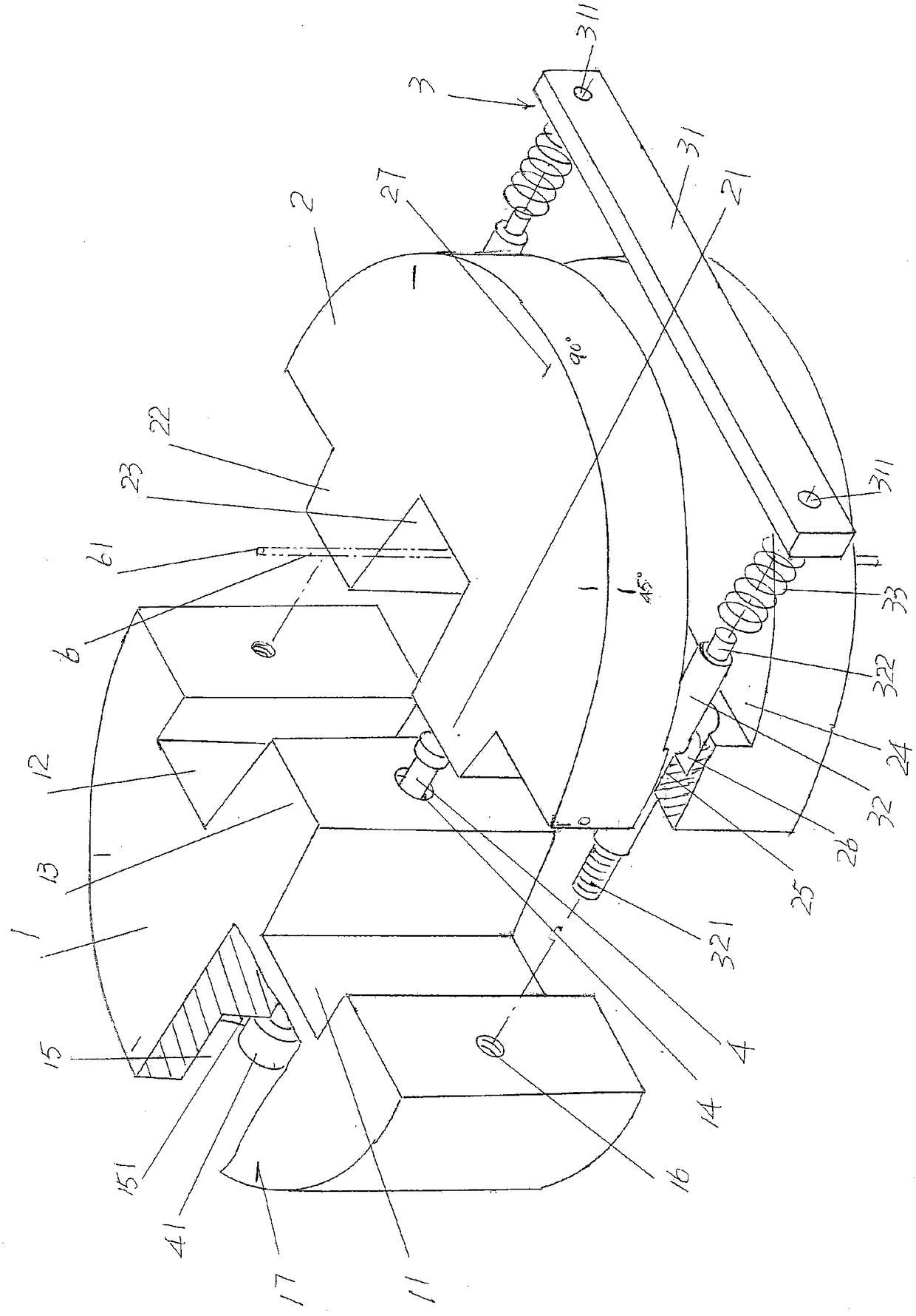
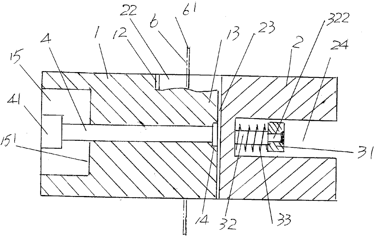
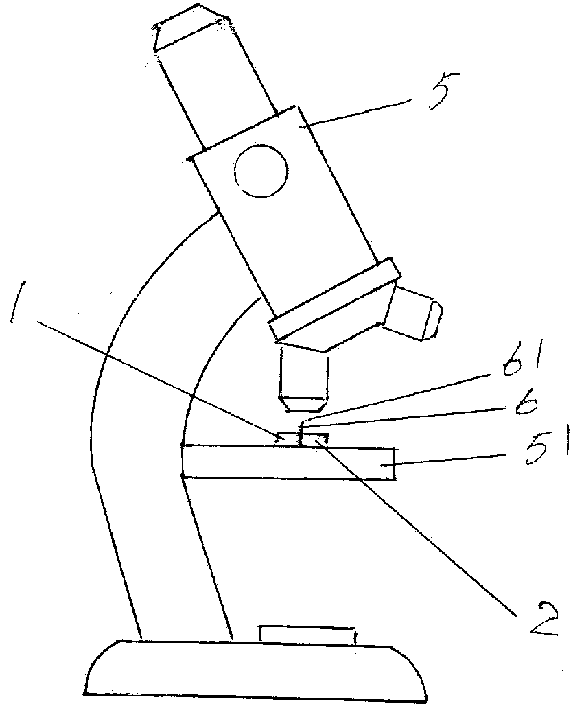
[0023] See figure 1 with figure 2 , Showing a left half-circle fiber clamping block 1 and a right half-circle fiber clamping block 2, the opposite sides of the left half-c...


PUM


Abstract

An optical fiber fixture for observing and analyzing the breaking point of an optical fiber belongs to the technical field of tools and fixture. The optical fiber fixture comprises left and right semicircular fiber clamping blocks, a fiber clamping block synchronous displacement connecting mechanism, and a push rod. The face-to-face sides of the left and right semicircular fiber clamping blocks are closed or separated. The fiber clamping block synchronous displacement connecting mechanism is arranged on the right semicircular fiber clamping block, and is connected with the left semicircular fiber clamping block. The push rod is arranged on the left semicircular fiber clamping block. When the left end of the push rod is pushed by external force, the right end of the push rod acts on the side, facing the left semicircular fiber clamping block, of the right semicircular fiber clamping block, and the left semicircular fiber clamping block and the right semicircular fiber clamping block areseparated against the counterforce of the fiber clamping block synchronous displacement connecting mechanism. When the action of the external force on the left end of the push rod is released, the left and right semicircular fiber clamping blocks actively move to each other and are closed under the action of the restoring force of the fiber clamping block synchronous displacement connecting mechanism. Optical fibers are prevented from getting out. The requirement for observing the end faces and side faces of the breaking point of an optical fiber is satisfied. The optical fiber fixture is small, and does not interfere with an observation device. The optical fiber fixture is simple in structure and easy to make.

Description

technical field [0001] The invention belongs to the technical field of fixtures, and in particular relates to an optical fiber fixture for observing and analyzing optical fiber breakage points. Background technique [0002] As known in the industry, in order to ensure the quality of optical fiber, optical fiber manufacturers need to observe and analyze the fractured part of the optical fiber, that is, the aforementioned fracture point (also called "crack source"). Because the optical fiber is very thin, the fracture point cannot be observed with the naked eye, so it is usually carried out under an optical microscope and the optical fiber needs to be rotated to adjust the angle of the optical fiber when observing the side of the optical fiber. Due to the lack of fixtures that can precisely position the optical fiber in the prior art, the observer often positions the optical fiber by pinching the fingers. The shortcomings of this method are: the observer's work intensity is hi...

Claims


Application Information

Patent Timeline
IPC IPC(8): G01M11/00
CPCG01M11/3163
Inventor 卫晓明刘世浩蒲冬林徐作臣谢康王继佩
Owner QINGHAI ZHONGLI OPTICAL FIBER TECH CO LTD
Why Eureka
Try Eureka