Optical path transmitting and reversing device and optical performance parameter detection system

A commutation device and optical path technology, applied in the field of lasers, can solve the problems of increased cost, large volume and quality of equipment, inconvenient handling, etc., and achieve the effect of saving energy, space consumption, etc., and improving pressure holding performance.

Pending Publication Date: 2018-06-01
ACAD OF OPTO ELECTRONICS CHINESE ACAD OF SCI
View PDF9 Cites 5 Cited by
  • Summary
  • Abstract
  • Description
  • Claims
  • Application Information

AI Technical Summary

Problems solved by technology

Usually, the transmission optical path from the laser to the lithography machine or optical detection equipment will be made into a fixed dedicated optical path, that is, one laser is used by one lithography or detection equipment, but when a laser needs to be used alternately by two devices At this time, due to the large volume and mass of these devices, it is inconvenient to carry. At this time, an optical path reversing device is needed, which can switch the laser to different devices according to the use requirements.
This kind of application generally does not appear in the production line of semiconductor factories, but it will appear in equipment research and development and optical inspection. Using a laser will also use more space, gas source, energy and other resources, which will increase the cost

Method used


Image

  • Optical path transmitting and reversing device and optical performance parameter detection system
  • Optical path transmitting and reversing device and optical performance parameter detection system
  • Optical path transmitting and reversing device and optical performance parameter detection system

Examples


Embodiment Construction

[0039] Hereinafter, exemplary embodiments of the present disclosure will be described in more detail with reference to the accompanying drawings. Although the drawings show exemplary embodiments of the present disclosure, it should be understood that the present disclosure can be implemented in various forms and should not be limited by the embodiments set forth herein. On the contrary, these embodiments are provided to enable a more thorough understanding of the present disclosure and to fully convey the scope of the present disclosure to those skilled in the art.

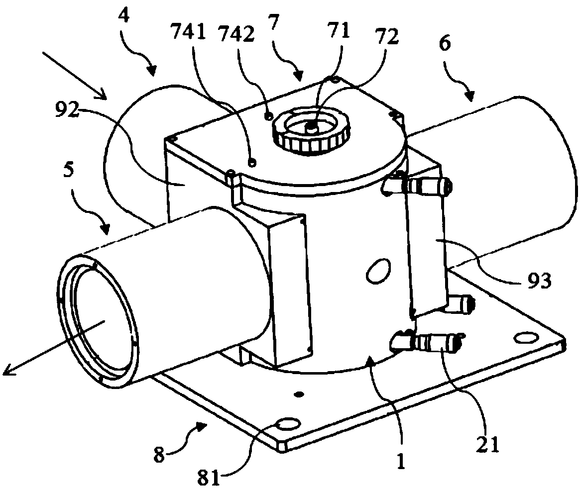
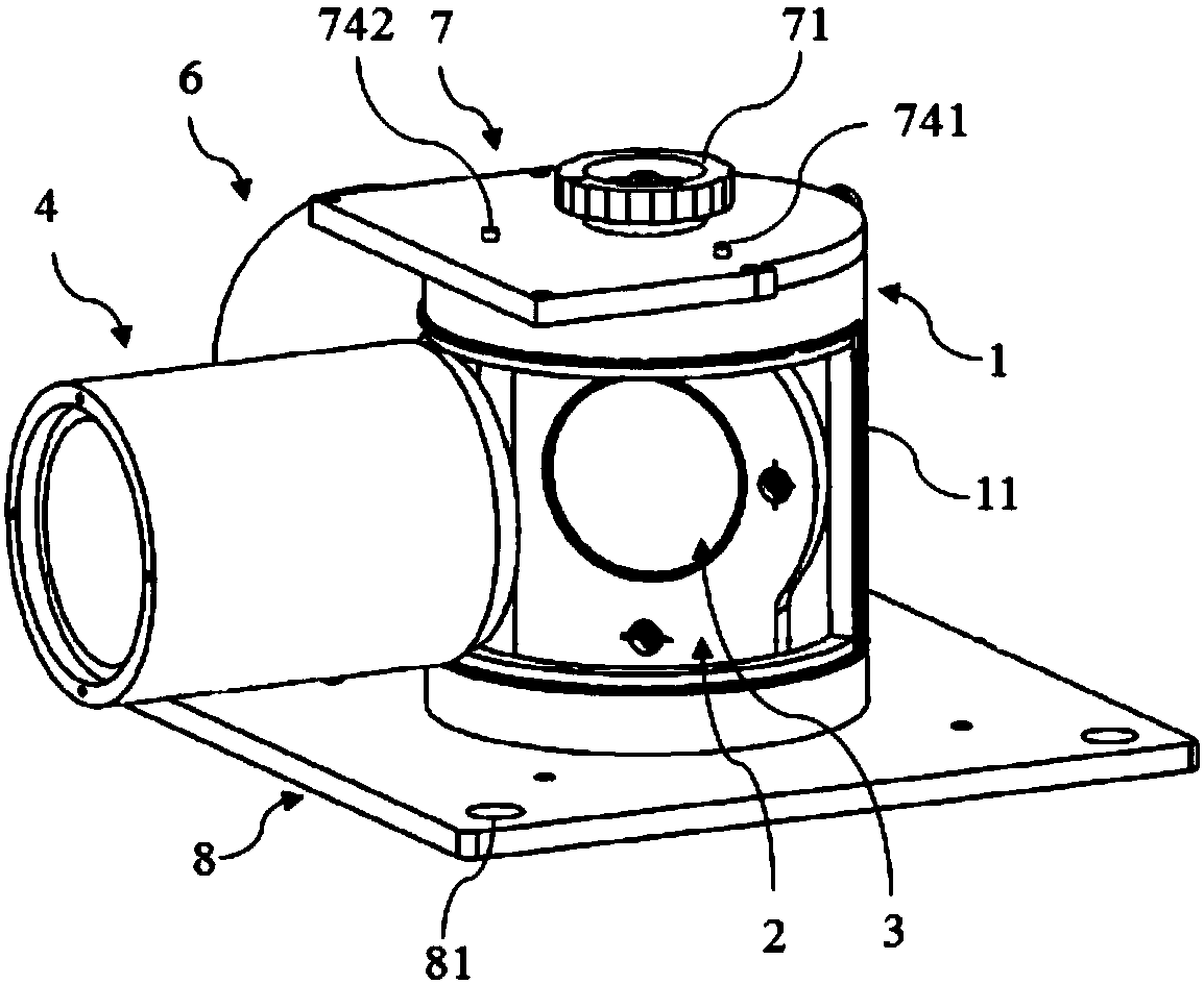
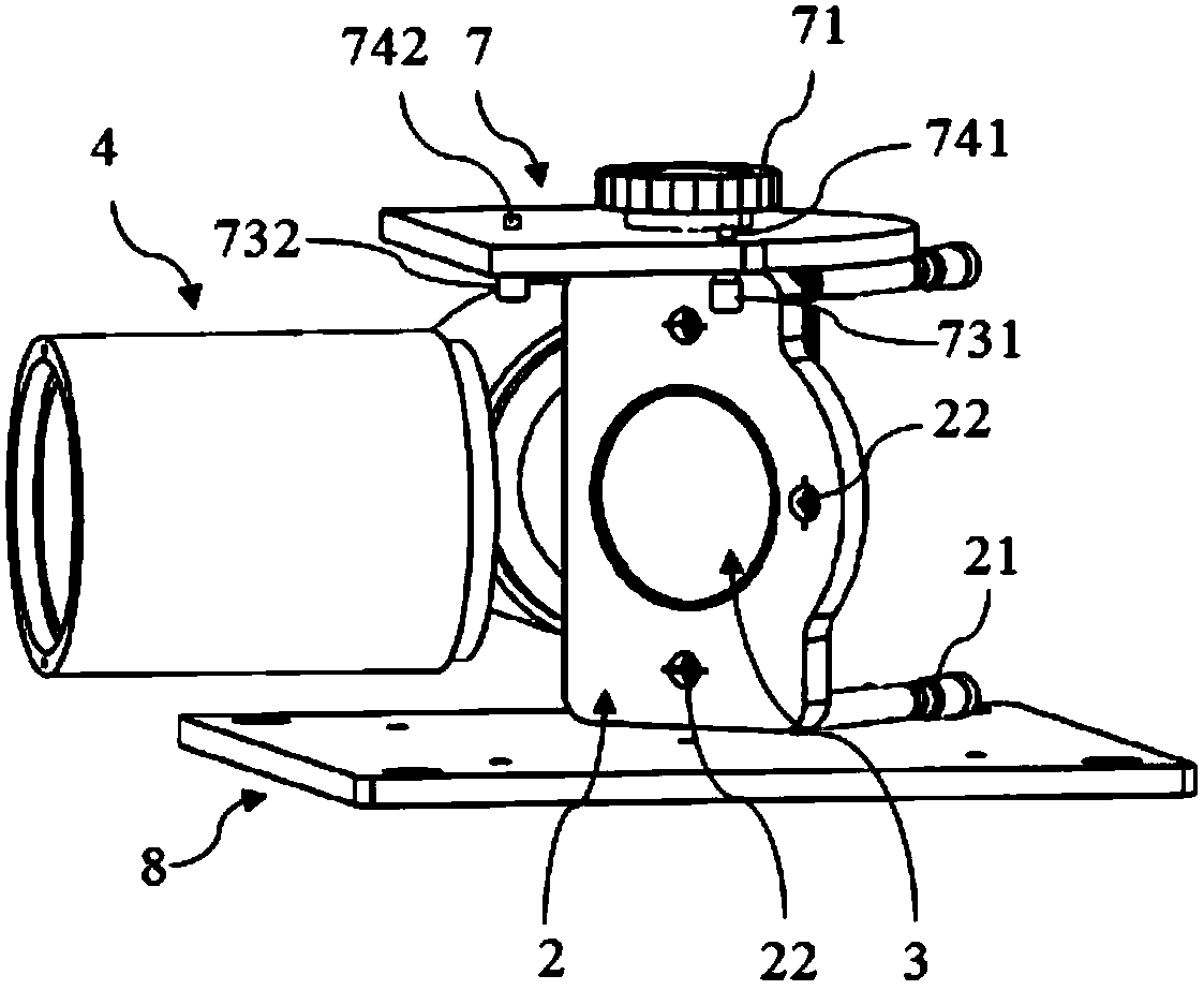
[0040] Figure 1 to Figure 6 It shows a schematic structural diagram of an optical path transmission commutation device according to an embodiment of the present invention. Such as Figure 1 to Figure 6 As shown, the device includes an input light tube 4, a reversing tube 1, an optical bracket 2, a first output light tube 5, a second output light tube 6, a top plate 7 and a bottom plate 8. The optical path transmis...


PUM


Abstract

The invention provides an optical path transmitting and reversing device. The optical path transmitting and reversing device comprises a input light cylinder, a reversing cylinder, an optical bracket,a first output light cylinder, a second output light cylinder, a top plate and a bottom plate, wherein the reversing cylinder is a partially hollow cylinder; the reversing cylinder is fixedly mountedon the bottom plate; the optical bracket is mounted inside the reversing cylinder; a reflector is fixedly mounted on the optical bracket; multiple side plates connected with the input light cylinder,the first output light cylinder and the second output light cylinder respectively are arranged around the reversing cylinder; the top plate is mounted on the top of the reversing cylinder; a turnplate capable of rotating the reversing cylinder is arranged on the top plate; a limiting mechanism is further arranged on the top plate, and the limiting mechanism can limit the optical bracket to be ina first state or a second state different from the first state. The invention further provides an optical performance parameter detection system comprising the optical path transmitting and reversingdevice.

Description

Technical field [0001] The invention relates to the field of laser technology, in particular to an optical path transmission reversing device and an optical performance parameter detection system. Background technique [0002] The lithography machine is mainly composed of projection objective lens, lighting system, mask table, workpiece table, light source and other main components. The light source of projection lithography machine covers a wide range of wavelengths, including ultraviolet g-line, i-line, extreme ultraviolet, deep ultraviolet, and extreme Ultraviolet rays, etc., currently the most widely used on the market is the 193nm (ArF) projection optical lithography machine. The light source module is usually separated from the whole machine, and can be a separate system. The light source to the lithography machine host is usually connected via a certain path of transmission light path. In order to prevent the laser from reacting with the air during the transmission proces...

Claims


Application Information

Patent Timeline
Patent Type & Authority Applications(China)
IPC IPC(8): G01N21/01
CPCG01N21/01G01N2201/0666G01N2021/015
Inventor 齐威齐月静王宇卢增雄杨光华
Owner ACAD OF OPTO ELECTRONICS CHINESE ACAD OF SCI
Why Eureka
Try Eureka