

Method and system for detecting bandwidth flatness and consistency of multichannel digital oscilloscope
A digital oscilloscope and detection method technology, applied in the direction of instruments, measuring devices, measuring electrical variables, etc., can solve time-consuming problems, achieve the effects of improving pass rate, shortening research and development time, and improving production efficiency
- Summary
- Abstract
- Description
- Claims
- Application Information
AI Technical Summary
Problems solved by technology
Method used
Image

Examples
Embodiment 1
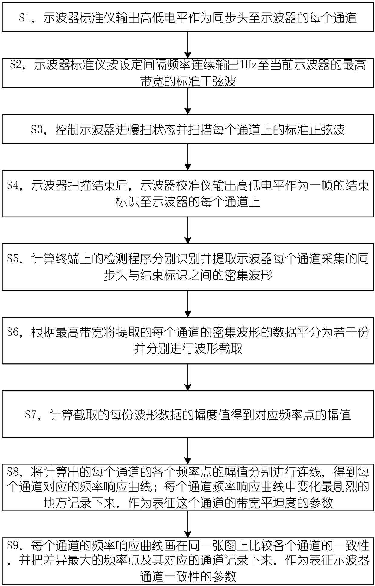
[0044] exist figure 1 In the flow chart shown, the program controls the oscilloscope calibrator to output a high and low level as the start mark, then continuously output a series of standard sinusoidal signals from low frequency to high frequency, and finally output a high and low level as the end mark, the program passes the waveform The recognition algorithm cuts off the high and low levels representing the start position and the high and low levels representing the end position from the waveform data collected from the oscilloscope. Through the interception operation, the collected original signal is processed into a signal that changes from sparse to dense. The oscilloscope should be set in the slow sweep state when acquiring this section of waveform, and ensure that the sampling rate of the oscilloscope at this time is much higher than twice the highest frequency of the output signal of the oscilloscope calibrator. This section of signal that changes from sparse to dens...
Embodiment 2
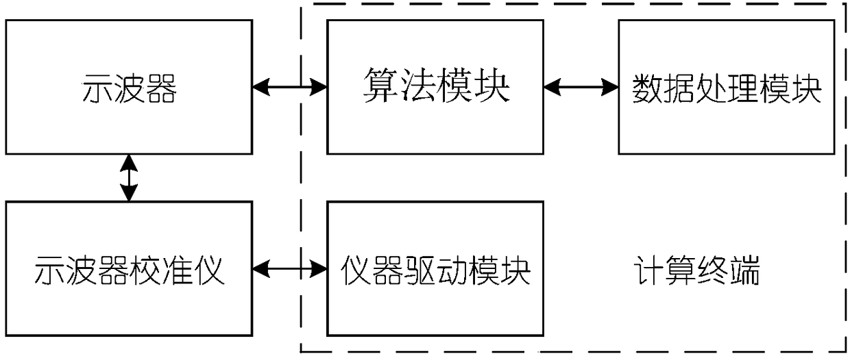
[0046] Because most of the oscilloscopes produced have not only one channel, but two or four, or more. This requires our detection system to detect the bandwidth flatness of multiple channels at the same time, and then calculate the consistency between each channel. In this way, it takes the same time to inspect multiple channels as to detect one channel, which greatly improves the production efficiency and greatly reduces the time cost. And it gives very intuitive and accurate results. The process steps are similar to those in Example 1, except that at this time, all channels of the oscilloscope must be connected to the output channels of the oscilloscope calibrator, and the oscilloscope calibrator is set to output multiple channels of the same signal at the same time, and the data of multiple channels are collected. Enter the calculation terminal for processing to obtain the frequency response curves of multiple channels. By drawing these curves together, it is very conveni...
PUM
 Abstract
Description
Claims
Application Information