Dual-DMD zooming infrared medium/long wave scene simulation system

A scene simulation and infrared technology, which is applied in optics, measuring devices, instruments, etc., can solve the problems of separate modulation of incident light in infrared bands, limited use range, and inability to test the anti-interference performance of infrared dual-band imaging systems, so as to improve energy utilization efficiency and integration, and the effect of avoiding interference between different optical paths

Active Publication Date: 2018-06-01
CHANGCHUN UNIV OF SCI & TECH
View PDF6 Cites 3 Cited by
  • Summary
  • Abstract
  • Description
  • Claims
  • Application Information

AI Technical Summary

Problems solved by technology

[0005] Although the above-mentioned infrared mid-wave / long-wave scene simulation system can be used to project infrared mid-wave and long-wave simulation scenes, since a single DMD cannot separately modulate the incident light of the two infrared bands, the detection in the infrared dual-band imaging system to be checked The detector can only receive infrared long-wave image light and infrared medium-wave image light with the same energy distribution. Although the overall brightness and darkness of the two different infrared band images will be different, it is still impossible to test the anti-interference performance of the infrared dual-band imaging system, which limits the scope of use

Method used


Image

  • Dual-DMD zooming infrared medium/long wave scene simulation system
  • Dual-DMD zooming infrared medium/long wave scene simulation system
  • Dual-DMD zooming infrared medium/long wave scene simulation system

Examples


Embodiment Construction

[0017] Exemplary embodiments of the present disclosure will be described in more detail below with reference to the accompanying drawings. Although exemplary embodiments of the present disclosure are shown in the drawings, it should be understood that the present disclosure may be embodied in various forms and should not be limited by the embodiments set forth herein. Rather, these embodiments are provided for more thorough understanding of the present disclosure and to fully convey the scope of the present disclosure to those skilled in the art.

[0018] The technical solution of the present invention will be further described below through examples.

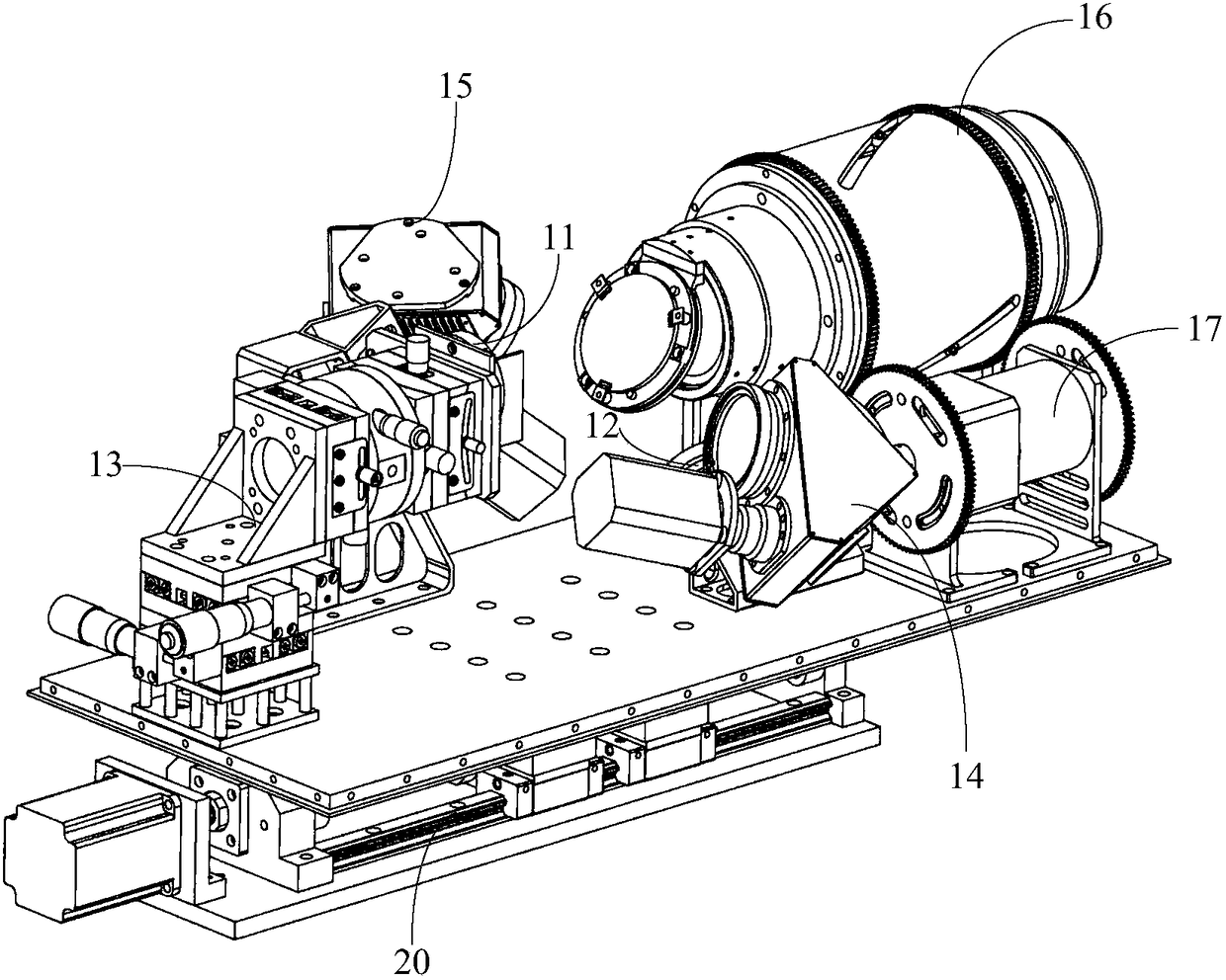
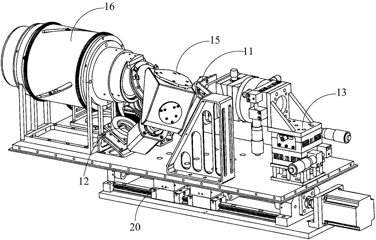
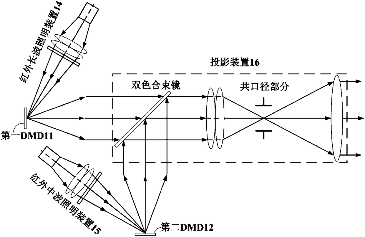
[0019] In this embodiment, a dual-DMD zoom infrared mid- / long-wave scene simulation system is provided. The technical principle is that the dual DMDs separately modulate the incident infrared long-wave and mid-wave light to generate infrared long-wave image light with different radiation information. and infrared mid-wave imag...


PUM


Abstract

The invention provides a dual-DMD zooming infrared medium / long wave scene simulation system, which comprises an optical engine and a first mobile device used for driving the optical engine to move axially along an optical axis, wherein the optical engine comprises an infrared long wave illumination device, an infrared medium wave illumination device, a first DMD, a second DMD, a second mobile device, a projection device and a driving assembly; the infrared long wave illumination device emits infrared long wave light which irradiates onto a first DMD target surface, and the infrared medium waveillumination device emits infrared medium wave light which irradiates onto a second DMD target surface; the first DMD modulates the infrared long wave light into infrared long wave image light, and the second DMD modulates the infrared medium wave light into infrared medium wave image light; the second mobile device adjusts a relative spatial position of the first DMD and the second DMD; the projection device comprises a common aperture section and a dual-color beam combiner; and the driving assembly drives a zooming group of the common aperture section of the projection device to do axial motion. The dual-DMD zooming infrared medium / long wave scene simulation system can project an infrared dual-band simulated scene, can simulate energy distribution difference of different infrared bandson an image plane in the scene, directly illuminates the two DMD target surfaces by means of the two illumination devices, avoids interference between different optical paths by adopting a spatial three-dimensional layout, and can effectively improve system energy utilization rate and integration degree.

Description

technical field [0001] The invention relates to the field of infrared dynamic scene simulation, in particular to a double DMD zoom infrared mid / long wave scene simulation system. Background technique [0002] The infrared dual-band imaging system can obtain image information of two infrared bands at the same time, and identify the real target by comparing the energy distribution difference of different infrared bands on the detector target surface in the scene, which not only inherits the advantages of the infrared single-band imaging system, The anti-interference ability is further improved. [0003] The performance of infrared dual-band imaging system depends on the selection of two bands, among which the combination of infrared mid-wave and long-wave is the best. In order to test and evaluate it, a matching infrared mid-wave / long-wave scene simulation system is proposed. During the test, the infrared medium / long-wave scene simulation system can project the infrared long-...

Claims


Application Information

Patent Timeline
Patent Type & Authority Applications(China)
IPC IPC(8): G02B27/00G01J5/08
CPCG01J5/0803G02B27/00
Inventor 潘越乔杨徐熙平
Owner CHANGCHUN UNIV OF SCI & TECH
Why Eureka
Try Eureka