A local centralized power supply and control device for batch pneumatic doors

A centralized power supply and control device technology, applied in the direction of circuit devices, electrical program control, sequence/logic controller program control, etc., can solve the problems of inability to merge cables, heavy cable laying construction workload, and large cable consumption. Achieve the effects of reducing cable length, good economic benefits, popularization and application value, and saving cable consumption

Active Publication Date: 2021-05-11
HENNAN ELECTRIC POWER SURVEY & DESIGN INST
View PDF6 Cites 0 Cited by
  • Summary
  • Abstract
  • Description
  • Claims
  • Application Information

AI Technical Summary

Problems solved by technology

Since the pneumatic doors are relatively scattered at the signal collection end, the DI and DO signals between different pneumatic doors 10 cannot be combined with cables
[0004] Assuming that each unit has 60 above-mentioned pneumatic doors 10, and each cable is calculated as 130m, the pneumatic doors of 2 units need cables: 60*2*130*2=31.2Km, the above-mentioned conventional power supply and control wiring design requires a large amount of cables , the cable laying construction workload is huge

Method used


Image

  • A local centralized power supply and control device for batch pneumatic doors
  • A local centralized power supply and control device for batch pneumatic doors
  • A local centralized power supply and control device for batch pneumatic doors

Examples


Embodiment Construction

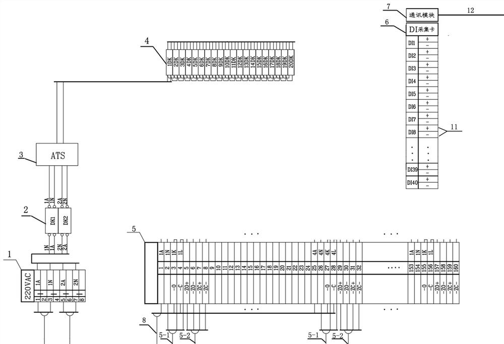
[0018] Such as image 3 As shown, a centralized power supply and control device for batch pneumatic doors is placed at the local end, including power supply incoming terminal block 1, main incoming power switch 2, dual power automatic switching device 3, power circuit switch 4, pneumatic The door power supply and control terminal block 5, the power supply incoming line terminal block 1, the main incoming line power switch 2, the dual power supply automatic switching device 3, the power circuit switch 4, the pneumatic door power supply and control terminal block 5 are connected in sequence, and the DI The signal data acquisition card 6 is connected to the power supply and control terminal block 5 of the pneumatic door and the communication module 7 .

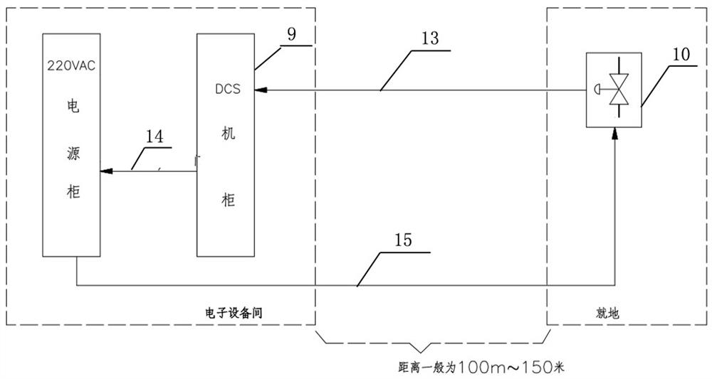
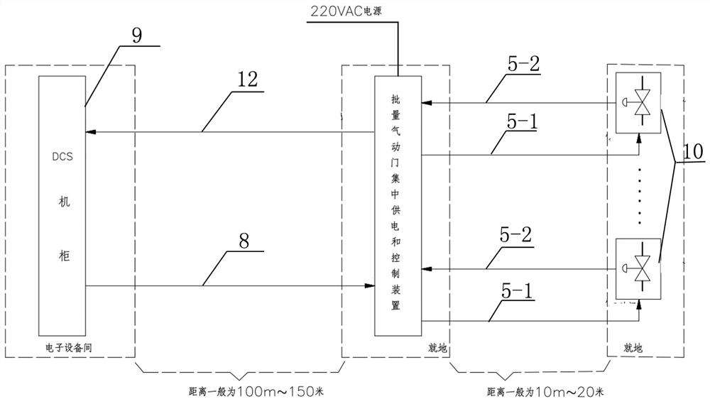
[0019] Such as figure 2 As shown in or 3, the device is powered by an external 220VAC power supply, and connects the DCS cabinet 9 and multiple pneumatic doors 10. On the one hand, it receives the DO control commands of multipl...


PUM


Abstract

The invention relates to a centralized power supply and control device for pneumatic doors in batches, including a power supply incoming terminal block, a main incoming power switch, a dual power supply automatic switching device, a power circuit switch, and a pneumatic door power supply and control terminal block. Power supply incoming line terminal block, main incoming line power switch, dual power supply automatic switching device, power circuit switch, pneumatic door power supply and control terminal block are connected sequentially, and DI signal data acquisition card is connected to pneumatic door power supply and control terminal block and communication module A plurality of A, K terminals and A, L terminals on the power supply and control terminal block of the pneumatic door are combined into one cable to connect the opening command and the closing command of the DCS cabinet respectively. By placing the local centralized power supply and control device of batch pneumatic doors at the local end, it can reduce the cable length from the local centralized power supply and control device of batch pneumatic doors to each pneumatic door, save the amount of cables, and have good economic benefits and popularization and application value.

Description

technical field [0001] The invention belongs to power plants or other industrial fields, and in particular relates to a local centralized power supply and control device for batch pneumatic doors. Background technique [0002] The flue gas system and the soda water system of the power plant have many relatively centralized batch pneumatic doors. For example: Jiaozuo Danhe Power Plant expands 2*1000000 kilowatt units in other places, and the large pressure small project has a total of 3*8=24 cooling dampers for the middle and lower burners on the front wall of the furnace, and 3*8 cooling dampers for the middle and lower burners on the rear wall. = 24, dozens of steam turbine body drain doors. These doors are fully open and fully closed pneumatic doors. Each pneumatic door needs a 220VAC power supply, and each pneumatic door has 1~2 DO signals and 2 DI signals connected to the control system DCS. [0003] The conventional design scheme for the power supply and control of th...

Claims


Application Information

Patent Timeline
Patent Type & Authority Patents(China)
IPC IPC(8): G05B19/04H02J3/00
CPCG05B19/04H02J3/00
Inventor 付俊芳丁玉玺徐荥冯雷韩卡蔡大泉欧伟张军民高玉玲
Owner HENNAN ELECTRIC POWER SURVEY & DESIGN INST
Why Eureka
Try Eureka