
Radio frequency switch device

A technology of radio frequency switches and devices, applied in semiconductor devices, electrical components, transistors, etc., can solve the problem that the performance of radio frequency switch devices needs to be improved.

Inactive Publication Date: 2018-06-01
SHANGHAI HUAHONG GRACE SEMICON MFG CORP
View PDF3 Cites 5 Cited by
  • Summary
  • Abstract
  • Description
  • Claims
  • Application Information

AI Technical Summary

Problems solved by technology

[0004] However, the performance of existing RF switching devices needs to be improved

Method used


Image

  • Radio frequency switch device
  • Radio frequency switch device
  • Radio frequency switch device

Examples


Embodiment Construction

[0029] The specific implementation manner of the present invention will be described in more detail below with reference to schematic diagrams. Advantages and features of the present invention will be apparent from the following description and claims. It should be noted that all the drawings are in a very simplified form and use imprecise scales, and are only used to facilitate and clearly assist the purpose of illustrating the embodiments of the present invention.

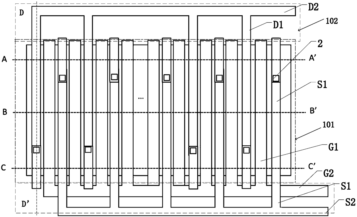
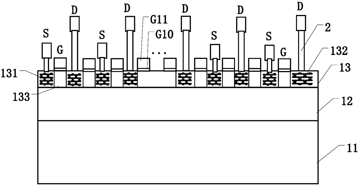
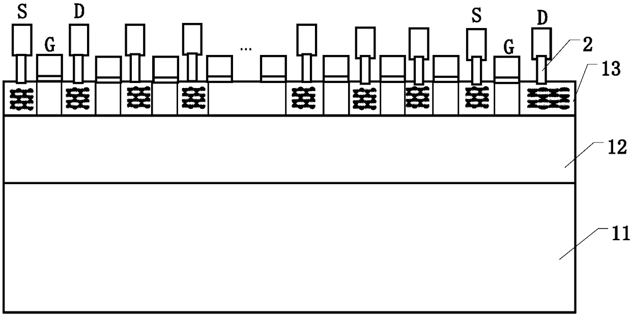
[0030] see figure 1 , which is a top view of the RF switching device provided by the embodiment, such as figure 1 As shown, the radio frequency switching device includes: a substrate; a gate structure G1, the gate structure G1 is located on the substrate; a source region 131 and a drain region 132, and the source region 131 and the drain region 132 are respectively located on the In the substrate on both sides of the gate structure G1; the source metal layer S1 and the drain metal layer D1, the source metal lay...


PUM


Abstract

A radio frequency switch device provided by the present invention is characterized in that in a part of area of a substrate, a source metal layer and a drain metal layer are located at different layers, by reducing the exactly facing area of the source metal layer and a grid structure, the equivalent off-state capacitance of the device is reduced, namely the capacitance of a part of transistors isreduced, so that the equivalent off-state capacitance of the device is reduced, and the figure of merit of the device is improved. Meanwhile, in the partial area of the substrate, the source metal layer and the drain metal layer are located at the different layers, in the rest area of the substrate, the source metal layer and the drain metal layer are still located at the same layer, and the equivalent conduction resistance of the device is not increased much.

Description

technical field [0001] The invention relates to the field of semiconductor manufacturing, in particular to a radio frequency switch device. Background technique [0002] The radio frequency switching device is a device used for signal switching in the communication field. It has the advantages of simple structure, wide application range, low cost, low power consumption, easy installation, and high reliability. It can be widely used in carrier telephone switching, cable television signal Switching, cable TV signal switch and other fields, when it is working, some areas are in the on state, and some areas are in the off state. [0003] Figure of Merit (FOM for short) is a characteristic test parameter for evaluating the performance or process of a radio frequency switching device. FOM=Ron*Coff, where Ron is the equivalent resistance value when the gate voltage of the device is equal to the on state of the device, and Coff is the equivalent capacitance value when the device is...

Claims


Application Information

Patent Timeline
Patent Type & Authority Applications(China)
IPC IPC(8): H01L27/088H01L29/417
CPCH01L27/088H01L29/41758
Inventor 刘张李
Owner SHANGHAI HUAHONG GRACE SEMICON MFG CORP
Learn More