Thermoelectric array
- Summary
- Abstract
- Description
- Claims
- Application Information
AI Technical Summary
Benefits of technology
Problems solved by technology
Method used
Image
Examples
embodiment 1
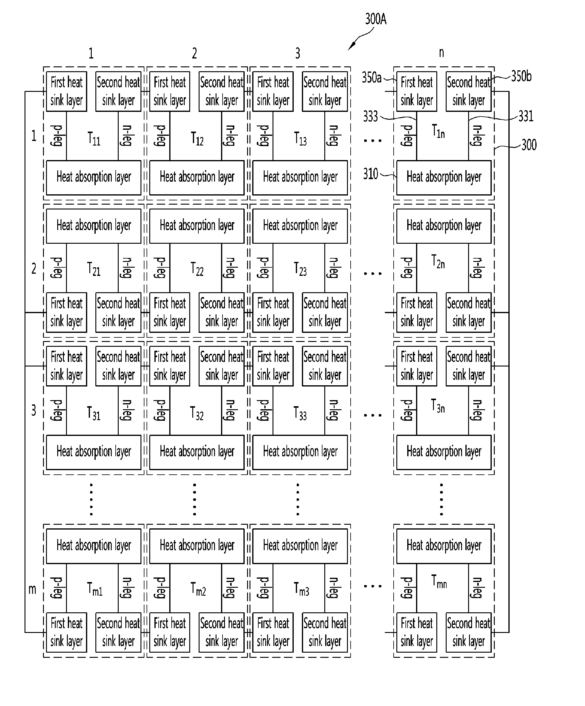
[0036]FIGS. 3A and 3B are top views of a thermoelectric array according to a first embodiment of the present invention.
[0037]To begin with, referring to FIG. 3A, a thermoelectric array 300A according to the first embodiment may include a plurality of thermoelectric elements 300 arranged in m rows and n columns (here, each of m and n is an integer equal to or more than 1). Each of the thermoelectric elements 300 may include a heat absorption layer 310, an n-type leg 331, a p-type leg 333, and first and second heat sink layers 350a and 350b. The heat absorption layers 310 of the thermoelectric elements 300 adjacently disposed in a row or column direction may be arranged adjacent to one another, and the heat sink layers 350a and 350b of the adjacent thermoelectric elements 300 in a row or column direction may be arranged adjacent to one another.
[0038]For brevity, in FIG. 3A, the respective thermoelectric elements 300 arranged in rows and columns are denoted by T11, T12, . . . , and Tmn...
embodiment 2
[0064]FIGS. 4A and 4B are top views of a thermoelectric array according to a second embodiment of the present invention.
[0065]To begin with, referring to FIG. 4A, a thermoelectric array 400A according to the second embodiment may include thermoelectric elements 300 arranged in one row and n columns (here, n is an integer equal to or more than 1).
[0066]Heat absorption layers 310 of adjacent thermoelectric elements 300 may be disposed adjacent to each other, and heat sink layers 350a and 350b of the adjacent thermoelectric elements 300 may be disposed adjacent to each other. Due to the above-described arrangement structure, thermal interference between adjacent thermoelectric elements 300 may be minimized.
[0067]Meanwhile, an output voltage of the thermoelectric array 400A of FIG. 4A may be controlled by adjusting the number of the thermoelectric elements 300 included in one row.
[0068]Also, each of the thermoelectric elements 300 of the thermoelectric array 400A shown in FIG. 4A includ...
embodiment 3
[0069]FIGS. 5A and 5B are top views of a thermoelectric array according to a third embodiment of the present invention.
[0070]To begin with, referring to FIG. 5A, a thermoelectric array 500A according to the third embodiment may include thermoelectric elements 300 arranged in m rows and one column (here, m is an integer equal to or more than 1).
[0071]Heat absorption layers 310 of adjacent thermoelectric elements 300 may be disposed adjacent to each other, and heat sink layers 350a and 350b of adjacent thermoelectric elements 300 may be disposed adjacent to each other. Due to the above-described arrangement, thermal interference between adjacent thermoelectric elements 300 may be minimized.
[0072]Meanwhile, an output current of the thermoelectric array 500A of FIG. 5A may be controlled by adjusting the number of the thermoelectric elements 300 included in one column.
[0073]Also, each of the thermoelectric elements 300 of the thermoelectric array 500A shown in FIG. 5A includes one n-type...
PUM
 Abstract
Description
Claims
Application Information
 - R&D
- Intellectual Property
- Life Sciences
- Materials
- Tech Scout
- Unparalleled Data Quality
- Higher Quality Content
- 60% Fewer Hallucinations
Browse by: Latest US Patents, China's latest patents, Technical Efficacy Thesaurus, Application Domain, Technology Topic, Popular Technical Reports.
© 2025 PatSnap. All rights reserved.Legal|Privacy policy|Modern Slavery Act Transparency Statement|Sitemap|About US| Contact US: help@patsnap.com


