Three-shaft linkage device

A technology of three-axis linkage and driving device, which is applied in the direction of transmission device, transmission device parts, belt/chain/gear, etc., can solve the problems of limiting motor acceleration, large load, and production efficiency can not be improved, so as to reduce motion load and production Efficiency improvement, the effect of improving efficiency

Pending Publication Date: 2018-06-05
恩纳基智能科技无锡有限公司
View PDF0 Cites 0 Cited by
  • Summary
  • Abstract
  • Description
  • Claims
  • Application Information

AI Technical Summary

Problems solved by technology

Although the idea involved is simple and clear, no matter what kind of driving mechanism is used, a huge load will be added, resulting in huge inertia that greatly limits the acceleration of the motor, so that the production efficiency cannot be improved, and the life of both the motor and the driving mechanism cannot be guaranteed.

Method used


Image

  • Three-shaft linkage device
  • Three-shaft linkage device

Examples


Embodiment Construction

[0013] Embodiments of the present invention will be described in detail below in conjunction with the accompanying drawings.

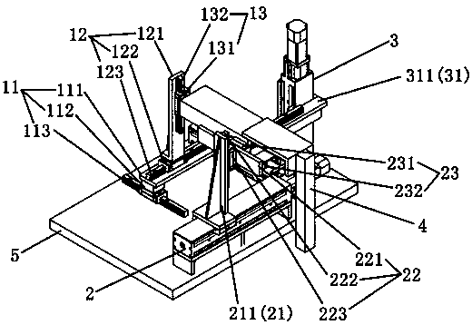
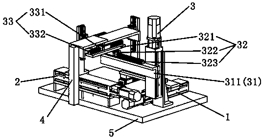
[0014] Such as figure 1 with figure 2 As shown, a three-axis linkage device includes a driving device, a guide sliding assembly and a working part 4 , the driving device is connected to the guiding sliding assembly, and the guiding sliding assembly is connected to the working part 4 .

[0015] The drive device includes an X-axis drive device 1, a Y-axis drive device 2 and a Z-axis drive device 3; the guide slide assembly includes an X-axis X-direction guide slide assembly 11 connected with the X-axis drive device, The X-axis X-direction guide slide assembly 11 is connected with the X-axis Y-direction guide slide assembly 12, the X-axis Y-direction guide slide assembly 12 is connected with the X-axis Z guide slide assembly 13, and the Y-axis drive device 2 is connected with the Y guide slide assembly 12. Axis Y-direction guide slide assembly 21, a Y-...


PUM


Abstract

The invention discloses a three-shaft linkage device and relates to the technical field of vacuum suction. The three-shaft linkage device comprises a driving device, a guiding sliding assembly and a working component, wherein the driving device is connected with the guiding sliding assembly, and the guiding sliding assembly is connected with the working component. According to the three-shaft linkage device, a certain guiding device is added between the connection of each driving shaft, so that the driving device of each shaft is independent, and no load is generated on other shafts; due to the existence of a guiding connecting device, each shaft can be in linkage, so that a mechanism greatly reduces the motion load during the movement, high-speed motion can be achieved, there is almost noload, the efficiency of each shaft is greatly improved, and thus the production efficiency is effectively improved.

Description

technical field [0001] The invention relates to the field of automation equipment, in particular to a three-axis linkage device. Background technique [0002] There has always been a problem in the semiconductor packaging industry, which is to use the traditional three-axis linkage mechanism, that is, to directly use mechanical fixed connections between the drive shafts to realize the transmission between the shafts. Although the idea involved is simple and clear, no matter what kind of driving mechanism is used, a huge load will be added, resulting in huge inertia that greatly limits the acceleration of the motor, so that the production efficiency cannot be improved, and the life of both the motor and the driving mechanism cannot be guaranteed. . Therefore, a new linkage mechanism is needed to solve the limitation of load on efficiency. Contents of the invention [0003] The purpose of the present invention is to overcome the above-mentioned problems of the prior art an...

Claims


Application Information

Patent Timeline
Patent Type & Authority Applications(China)
IPC IPC(8): F16H57/00F16H25/20
CPCF16H57/00F16H25/20F16H2025/204F16H2025/2075
Inventor 王军曾义
Owner 恩纳基智能科技无锡有限公司
Why Eureka
Try Eureka