Device and method for in-situ testing of earth pressure

A technology of in-situ testing and testing methods, applied in measuring devices, using stable tension/pressure to test material strength, instruments, etc., can solve problems such as distortion of measurement results, and achieve the effect of clear mechanical concept

Pending Publication Date: 2018-06-05
SHANGHAI GEOTECHN INVESTIGATIONS & DESIGN INST
View PDF8 Cites 8 Cited by
  • Summary
  • Abstract
  • Description
  • Claims
  • Application Information

AI Technical Summary

Problems solved by technology

[0004] The object of the present invention is to provide a kind of soil pressure in-situ test device and its test method according to the deficiencies of the above-mentioned prior art. The device uses hydraulic transmission to measure the soil pressure, and the influence of the surrounding soil layer is small during the installation process. , which effectively solves the problem of measurement result distortion existing in the prior art

Method used


Image

  • Device and method for in-situ testing of earth pressure
  • Device and method for in-situ testing of earth pressure
  • Device and method for in-situ testing of earth pressure

Examples


Embodiment 1

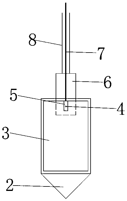
[0031] Embodiment 1: as figure 1 , 2 As shown, the present embodiment specifically relates to an in-situ earth pressure testing device, which includes a back panel 2; groove; the front of the back panel 2 is also provided with an elastic contact panel 1, and the elastic contact panel 1 and the groove are enclosed to form a sealed hydraulic cavity 3; the back panel 2 is provided with a hydraulic gauge 5, and the hydraulic gauge 5 passes through the pressure transmission tube 4 It communicates with the hydraulic cavity 3; the hydraulic cavity 3 and the pressure transmission pipe 4 are filled with liquid; the hydraulic gauge 5 is used to measure the liquid pressure inside the hydraulic cavity 3.

[0032] like figure 1 , 2 As shown, the elastic contact panel 1 is a metal plate with a relatively thin thickness; the elastic contact panel 1 can produce slight deformation under the action of earth pressure, resulting in an increase in the pressure inside the hydraulic cavity 3; Th...

Embodiment 2

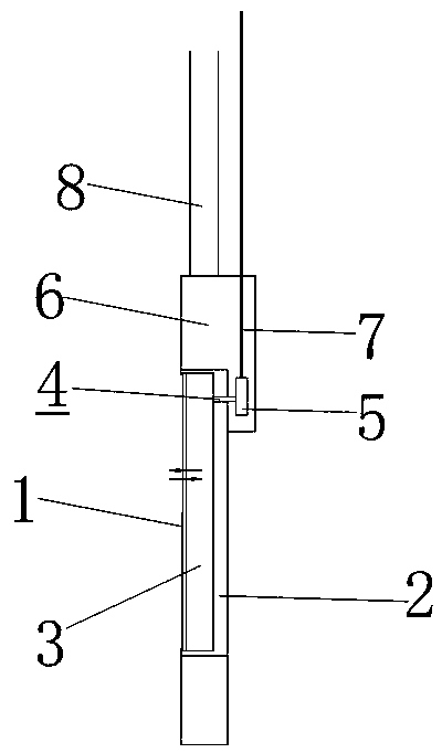
[0046] Embodiment 2: as Figure 5 , 6 As shown, the main difference between this embodiment and Embodiment 1 lies in the shape of the bottom of the back panel 2 and the installation method of the hydraulic gauge 5; in this embodiment, the bottom of the back panel 2 is wedge-shaped; in this embodiment, the hydraulic cavity 3 The top of the top is provided with a pressure transmission tube 4; the hydraulic gauge is installed on the top of the back panel 2, and is connected with the hydraulic cavity through the pressure transmission tube 4; the signal line of the hydraulic gauge 5 is arranged on the outside of the rigid rod 8; in addition, the present embodiment The middle rigid rod 8 is directly connected to the top of the back panel 2, and the top of the back panel 2 has no connection end.

Embodiment 3

[0047] Embodiment 3: as Figure 7 , 8 As shown, the main difference between this embodiment and Embodiment 1 lies in the installation method of the hydraulic gauge 5; in this embodiment, the hydraulic gauge 5 is embedded on the inner surface of the hydraulic cavity 3, and the hydraulic gauge 5 is directly connected to the hydraulic cavity 3; In addition, in this embodiment, the bottom of the back panel 2 is an arc-shaped structure.


PUM


Abstract

The invention discloses a device and method for in-situ testing of an earth pressure. The device for in-situ testing of the earth pressure comprises a back panel, wherein the front face of the back panel is provided with a groove, an elastic contact panel is packaged and arranged on an open surface of the groove, and the elastic contact panel and the groove are enclosed to form a closed hydrauliccavity; and the hydraulic cavity is communicated with a hydraulic pressure meter, and the hydraulic cavity is filled with liquid. The device and the method provided by the invention have the advantages that the earth pressure is measured by adopting a hydraulic conduction mode, the influence of surrounding soil layers in a mounting process is small, and the problem that a measurement result is distorted in the prior art is effectively solved.

Description

technical field [0001] The invention belongs to the field of civil engineering, and in particular relates to an in-situ testing device for earth pressure and a testing method thereof. Background technique [0002] The pressure state test in the soil is one of the important methods to evaluate the safety of geotechnical engineering structures and verify whether the design theory is reasonable. At present, the commonly used earth pressure test method is mainly carried out by embedding earth pressure cells in the soil. The traditional pressure cell The vibrating wire type earth pressure cell is used. During the test, the earth pressure cell is placed to the required depth after the hole is formed by pre-drilling, and then the soil is filled with the soil around the earth pressure cell by backfilling the hole. The surrounding undisturbed soil The earth pressure is transmitted to the contact surface of the earth pressure cell through the backfill soil, and the change of the earth...

Claims


Application Information

Patent Timeline
Patent Type & Authority Applications(China)
IPC IPC(8): G01N3/12G01N3/02
CPCG01N3/02G01N3/12G01N2203/0048
Inventor 顾国荣马忠政杨石飞路家峰辛海红苏辉
Owner SHANGHAI GEOTECHN INVESTIGATIONS & DESIGN INST
Why Eureka
Try Eureka