A wire grid unit and its protection device

A protection device, the technology of the first wire grid, applied in polarizing elements, optical elements, nonlinear optics, etc., can solve the problems of difficult processing of wire grid splicing devices, easily deformed splicing gaps, etc., to increase the effective light transmission area, improve Cumulative dose uniformity, easy processing effect

Active Publication Date: 2020-11-20
SHANGHAI MICRO ELECTRONICS EQUIP (GRP) CO LTD
View PDF5 Cites 0 Cited by
  • Summary
  • Abstract
  • Description
  • Claims
  • Application Information

AI Technical Summary

Problems solved by technology

[0026] The invention provides a wire grid unit and its protection device, which are used to solve the problems of difficult processing, easy deformation at high temperature and large splicing gap of the wire grid splicing device

Method used


Image

  • A wire grid unit and its protection device
  • A wire grid unit and its protection device
  • A wire grid unit and its protection device

Examples


Embodiment 1

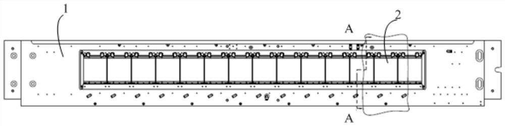
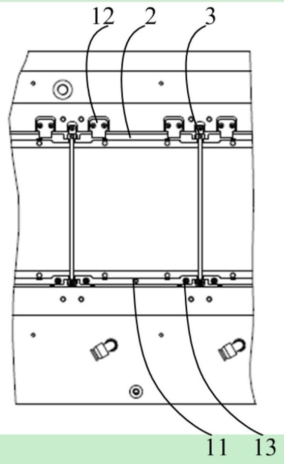
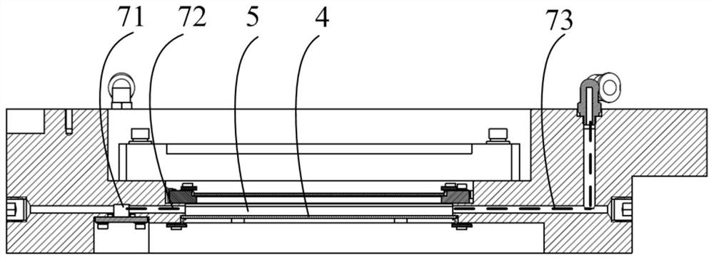
[0060] See Figure 1~3 ,among them, figure 2 Yes figure 1 A partial enlarged view of a single wire grid unit in image 3 It is a cross-sectional view from the A-A direction. An open wire grid splicing protection device includes a frame 1, a plurality of wire grid units 2, a frame light-blocking strip 3, a sealing element 4 and a gas path system. The wire grid unit 2 is in a straight shape They are arranged on the frame 1. In this embodiment, fourteen of the wire grid units 2 are arranged, and the frame light-blocking strips 3 are located under the splicing seams between the wire grid units 2 and are arranged at all On the frame 1, the frame light blocking strip 3 is not in contact with the wire grid unit 2, the width of the frame light blocking strip 3 is not less than the width of the splicing seam, and the sealing member 4 is arranged on the The frame 1 forms an integrated chamber 5 with the frame 1, the frame light-blocking strip 3 and the wire grid unit 2, and the gas path ...

Embodiment 2

[0074] See Figure 6 ~ Figure 10 The difference between the second embodiment and the first embodiment is that one end of the wire grid unit 2 locates the first wire grid support 22 through the positioning pin 11 provided on the frame 1, and is supported by the first wire grid The pressing nails 14 on the member 22 and the second wire grid supporting member 23 press the wire grid unit 2 to position the wire grid unit 2 on the frame 1, and the pressing nail 14 can fix the wire Location of gate unit 2. In this embodiment, there are three compression pins 14, and the center of the figure formed by the positioning pins 11 and the three compression pins 14 coincides with the projection of the center of gravity of the wire grid 21 on the scale surface of the wire grid. . The second wire grid support 23 is provided with a shift lever 15 corresponding to the position of the positioning pin 11, and the wire grid 21 is adjusted in-plane rotation through the shift lever 15.

[0075] The ...


PUM

PropertyMeasurementUnit
elastic modulusaaaaaaaaaa
densityaaaaaaaaaa
widthaaaaaaaaaa

Abstract

The invention discloses a wire gating unit. The wire gating unit comprises a wire gating, a first wire gating support part, a second wire gating support part and wire gating pressing sheets; the wiregating is arranged on the first wire gating support part and the second wire gating support part which are arranged on the two sides of the opposite side of a wire grating scale surface respectively,the wire gating scale surface faces the first wire gating support part and the second wire gating support part, and the wire gating is fixed through the wire gating pressing sheets fixed to the firstwire gating support part and the second gating support part. The wire gating unit is simple in structure and wide in application range. The invention further discloses a protection device of the wiregating unit. The protection device adopts an assembly type structure, the effective light transmission area of the wire gating is increased, and the accumulated dose uniformity of the protection device in the whole machine is improved.

Description

Technical field [0001] The invention relates to a wire grid unit and a protection device thereof. Background technique [0002] The core component of the LCD optical alignment equipment is the wire grid component part with the same polarization direction. Currently, it is subject to the level of wire grid manufacturing. The wire grid sizes available at home and abroad are generally 120mm×120mm, 100mm×100mm and 120mm×100mm. Kind. The current world mainstream LCD screen production size has reached 4.5G and 6G, so it is necessary to design a reliable wire grid splicing protection unit for the wire grid splicing protection device. [0003] The main performance requirements for the polarizing module of optical alignment equipment are generally: [0004] 1. Polarization angle error: ±870urad; [0005] 2. Extinction ratio: ≥100:1; [0006] 3. Combined lighting and other modules, the uniformity of cumulative dose of light after passing through the wire grid: ≤5%. [0007] Among them, the cumu...

Claims


Application Information

Patent Timeline
Patent Type & Authority Patents(China)
IPC IPC(8): G02F1/1335G02B5/30
CPCG02B5/3058G02F1/133528G02F1/133548G02F1/1337
Inventor 熊金磊
Owner SHANGHAI MICRO ELECTRONICS EQUIP (GRP) CO LTD
Why Eureka
Try Eureka