Automatic drive direction control system and method based on high-precision navigation and positioning system

A technology of automatic driving control, navigation and positioning, applied in non-electric variable control, two-dimensional position/lane control, vehicle position/route/altitude control, etc. and other problems, to achieve the effect of solving untimely direction control, good economy and feasibility, and improved comfort

Inactive Publication Date: 2018-06-05
DONGFENG MOTOR CORP HUBEI
View PDF10 Cites 5 Cited by
  • Summary
  • Abstract
  • Description
  • Claims
  • Application Information

AI Technical Summary

Problems solved by technology
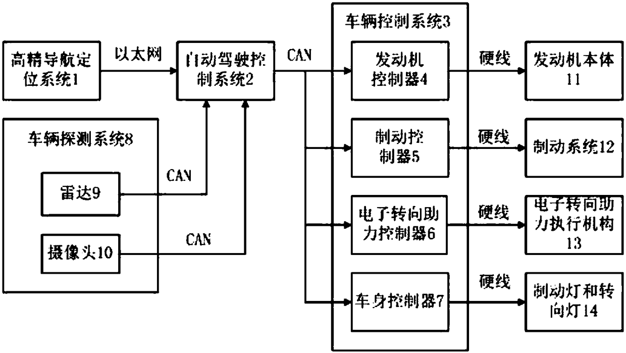
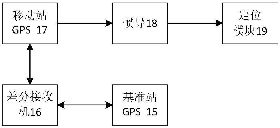
Since the above sensors cannot effectively identify curves and ramps beyond the distance (300 meters) in extreme weather such as rain, snow, fog, etc., the distance is too close when the driver finds it, and traffic accidents are likely to occur, which seriously affects vehicles, The life safety of members, property and pedestrians, but also has an impact on the comfort of autonomous driving

Method used


Image

  • Automatic drive direction control system and method based on high-precision navigation and positioning system
  • Automatic drive direction control system and method based on high-precision navigation and positioning system
  • Automatic drive direction control system and method based on high-precision navigation and positioning system

Examples


example 1

[0029] Example 1: Vehicle decimeter-level positioning coordinates D (X, Y, Z), the distance between the vehicle and the speed limit sign is 49.99 meters; the distance between the front speed limit sign and the vehicle recognized by the vehicle camera and radar is 50.55 meters, and D( The coordinates of X, Y, Z) are D'(X, Y+50.55-49.99, Z). Since the laser radar ranging accuracy is less than 2cm, the corrected vehicle positioning accuracy reaches centimeter-level accuracy.

example 2

[0030] Example 2: The positioning coordinates D (X, Y, Z) of the vehicle at the decimeter level, the distance between the vehicle and the lane line is found to be 0.35 meters on the high-precision map; the distance between the vehicle and the lane line recognized by the camera is 0.54 meters; the coordinate D can be corrected (X,Y,Z) is D'(X+0.54-0.35,Y,Z). Since the ranging accuracy of the high-definition camera is less than 3cm, the corrected vehicle positioning accuracy reaches the centimeter level.

example 3

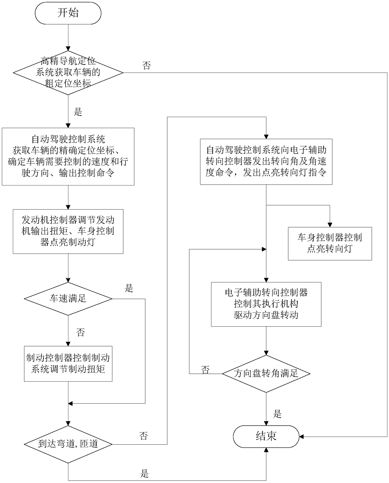
[0031] Example 3: The current vehicle speed V1 is 60km / h. Through the high-precision navigation and positioning system, radar, and camera, it is found that the distance D of the curve ahead is 100m, the speed limit V2 of the curve is 30km / h, and the time for the vehicle to reach the curve is t=D / V1*3600 / 1000, calculate the deceleration a=(V2-V1) / t*1000 / 3600 when the vehicle speed changes from V1 to V2, compare it with the anti-drag deceleration a' generated by setting the accelerator pedal of the engine system to zero, if a < a', the vehicle braking is accomplished by the engine system; otherwise, the vehicle braking is accomplished jointly by the engine system and the braking system.

[0032] Steering wheel steering angle calculation: r=R / d; (d is a constant calculated by the vehicle steering system).

[0033] Steering wheel angular velocity calculation: ɑ=f(e, r); (f(e, r), e is a constant calculated by the vehicle steering system, f(e, r) is the calculation function of ang...


PUM


Abstract

The invention discloses an automatic drive direction control system and method based on a high-precision navigation and positioning system. The control system comprises the high-precision navigation and positioning system which is used for obtaining coarse positioning coordinates of a vehicle according to the positioning data of the high-precision navigation and positioning system; an automatic drive controls system which is used for receiving the information of the high-precision navigation and positioning system, and obtaining the precise positioning coordinates of the vehicle, the curvatureof a bent lane in the moving direction of the vehicle, the traffic mark information and the data of the distance between the vehicle and the bent lane through the combination of the data of a vehicledetection system and a high-precision map of the vehicle, and determining the to-be-controlled speed and moving direction of the vehicle according to the current speed and the obtained data; and a vehicle control system which is used for controlling the reduction of the speed and controlling the moving direction to change. According to the invention, the system carries out the precise positioningof the vehicle, obtains the control information of the vehicle in advance, and controls the vehicle control system to take measures for adjusting the speed and moving direction. The system is betterin economic performance and feasibility, and greatly improves the safety and comfort of an autonomous vehicle.

Description

technical field [0001] The invention belongs to the technical field of automobile automatic driving, and in particular relates to an automatic driving direction control system and method based on a high-precision navigation and positioning system. Background technique [0002] Autopilot technology has gone through decades of development from its inception to the present. Driving on flat roads, with the help of sensors such as lidar, millimeter-wave radar, and cameras to identify the road, the automatic driving function can be better realized. Since the above sensors cannot effectively identify curves and ramps beyond the distance (300 meters) in extreme weather such as rain, snow, fog, etc., the distance is too close when the driver finds it, and traffic accidents are likely to occur, which seriously affects vehicles, The life safety of members, property and pedestrians also affects the comfort of autonomous driving. Contents of the invention [0003] The purpose of the ...

Claims


Application Information

Patent Timeline
Patent Type & Authority Applications(China)
IPC IPC(8): G05D1/02
CPCG05D1/0214G05D1/024G05D1/0246G05D1/0257G05D1/0276G05D1/0278G05D2201/02
Inventor 冯春李凯冯超方强曹恺杨航杨显国于先林
Owner DONGFENG MOTOR CORP HUBEI
Why Eureka
Try Eureka