Guard bar cutting device
A cutting device and guardrail technology, which is applied in the direction of sawing machine, sawing machine accessories, metal sawing equipment, etc., can solve the problems of low cutting quality, different pipe materials, and pipe shaking, etc., so as to improve the cutting quality and cut the length accurately , Improve the effect of cutting precision
Active Publication Date: 2018-06-08
临沂经济开发有限公司
View PDF6 Cites 6 Cited by
- Summary
- Abstract
- Description
- Claims
- Application Information
AI Technical Summary
Problems solved by technology
[0005] The above solution can realize the fixed-length cutting of the pipe, but the length of the pipe required in actual production is often different; and the device directly cuts the pipe without clamping the pipe, which will cause the pipe to shake, so that the cutting quality is not high , may also lead to security issues
Method used
View moreImage
Smart ImageViewing Examples
Examples
Embodiment Construction
[0018] The present invention will be described in further detail below by means of specific embodiments:
Login to View More PUM
 Abstract
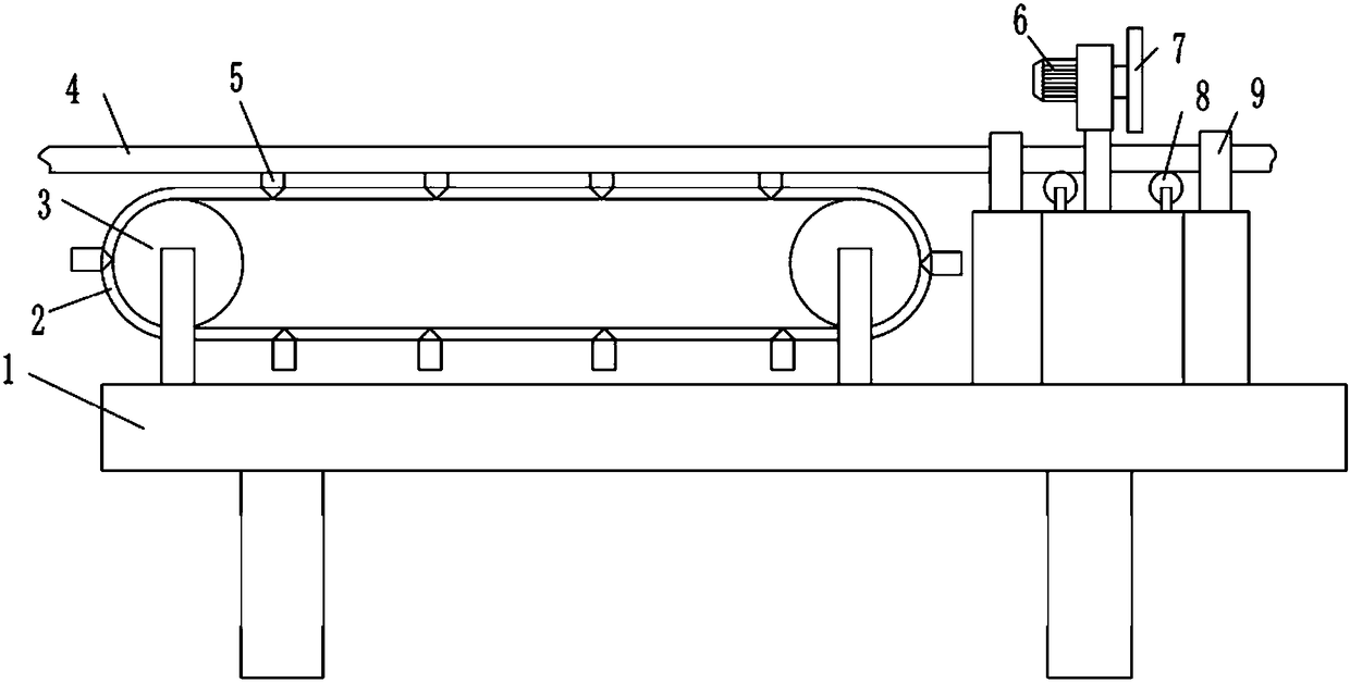
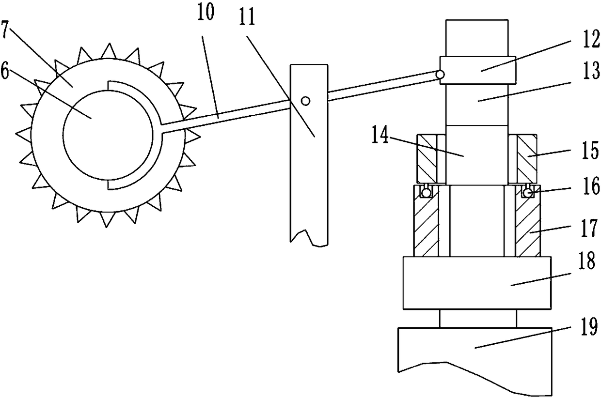
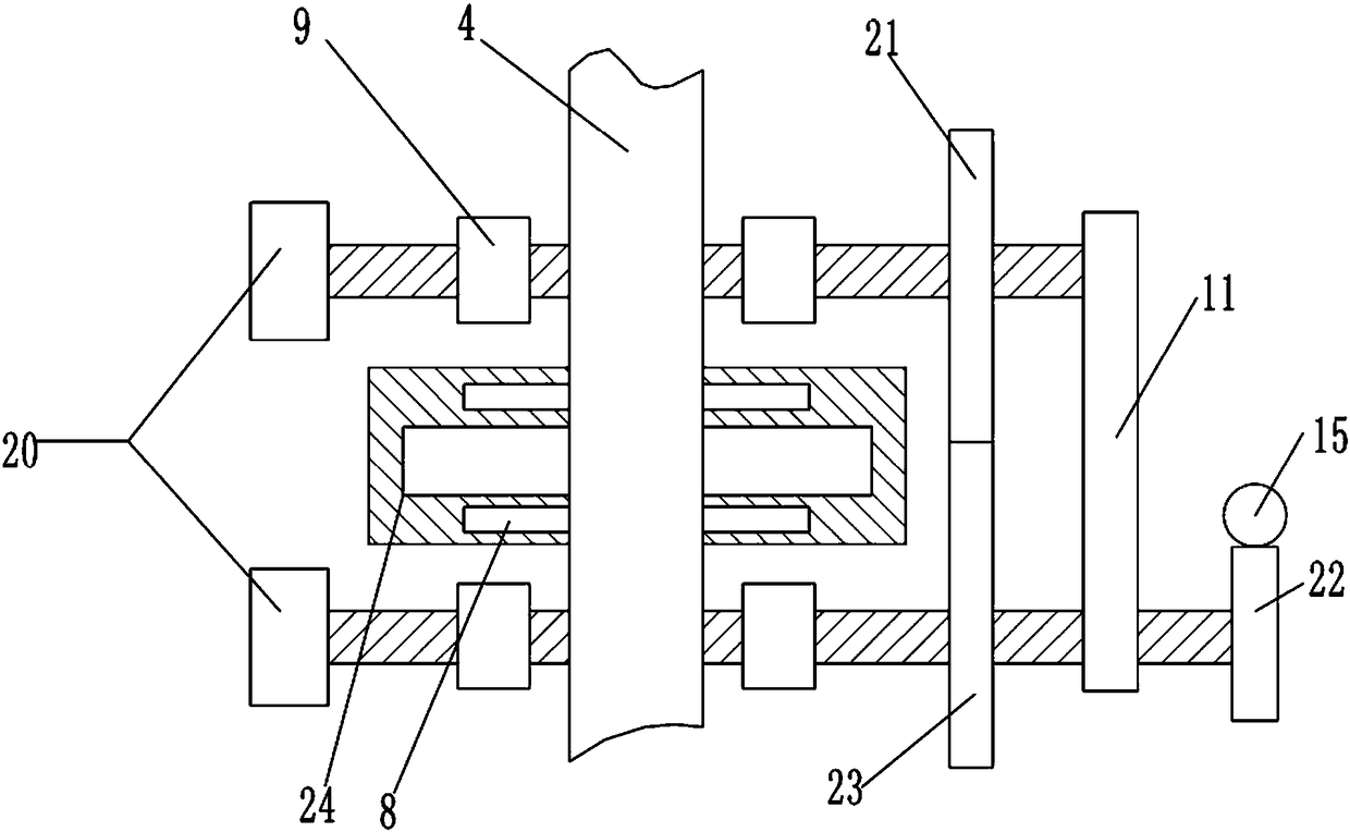
The invention belongs to the technical field of guard bar machining, and particularly discloses a guard bar cutting device. The device includes a worktable, and a conveying mechanism used for conveying pipe materials and a cutting mechanism used for cutting the pipe materials are arranged on the worktable. The conveying mechanism includes a conveyor belt, multiple V-shape locating blocks are movably connected to the conveyor belt, and each V-shaped locating block is provided with an approaching switch. The cutting mechanism includes a supporting frame and a second motor, an output shaft of thesecond motor is fixedly provided with an air expanding shaft, and a worm sleeves the air expanding shaft. A first lead screw is arranged on the air expanding shaft, and a first nut support is screwedwith the first lead screw. A connecting rod is hinged to the first nut support and the supporting frame and provided with the cutting mechanism. A worm gear is meshed with the worm, a bidirectional lead screw is connected to the center of the worm gear, second nut supports are screwed at both ends of the bidirectional lead screw, and clamping blocks are connected to both the two second nut supports. According to the scheme, cutting of the pipe materials can be achieved according to different length demands, and high cutting quality is ensured.
Description
technical field [0001] The invention belongs to the technical field of guardrail processing, and in particular relates to a guardrail cutting device. Background technique [0002] Guardrails are mainly used for the protection and protection of equipment and facilities in factories, workshops, warehouses, parking lots, commercial areas, public places and other occasions. Guardrails can be seen everywhere in our lives. The columns of the guardrail are fixed to the ground by expansion bolts. It is usually installed on both sides of the logistics channel, around the production equipment, in the corner of the building, on both sides of the door and the edge of the cargo platform, etc. Effectively reduce the damage to equipment and facilities caused by accidental impact when transporting equipment back and forth. Guardrail materials include: aluminum alloy, malleable steel (ductile iron), carbon steel (sprayed or galvanized), stainless steel, plastic steel, zinc steel, PVC and ...
Claims
Login to View More Application Information
Patent Timeline
 Patent Type & Authority Applications(China)
IPC IPC(8): B23D47/02B23D59/02B23Q17/00
Inventor 周强周琪
Owner 临沂经济开发有限公司
Features
- R&D
- Intellectual Property
- Life Sciences
- Materials
- Tech Scout
- Unparalleled Data Quality
- Higher Quality Content
- 60% Fewer Hallucinations
Learn More Browse by: Latest US Patents, China's latest patents, Technical Efficacy Thesaurus, Application Domain, Technology Topic, Popular Technical Reports.
© 2025 PatSnap. All rights reserved.Legal|Privacy policy|Modern Slavery Act Transparency Statement|Sitemap|About US| Contact US: help@patsnap.com


