Lubricating grease filling equipment

A technology for filling equipment and lubricating grease, applied in mechanical equipment, lubricating parts, manually supplying lubricant, etc., can solve the problems of being unable to carry out, waste, etc., achieve large market promotion value and economic benefits, and reduce waste and pollution , the effect of easy maintenance

Inactive Publication Date: 2018-06-08
JIANGSU SHORTCUT DISABILITIES LUBRICANT
View PDF0 Cites 0 Cited by
  • Summary
  • Abstract
  • Description
  • Claims
  • Application Information

AI Technical Summary

Problems solved by technology

[0003] The present invention aims to solve the above-mentioned problems. The problem of being unable to carry out is solved by setting a storage battery. It can be used more conveniently by using an electric telescopic rod. By using a distance sensor, the filling amount can be clearly known. By using a pressure sensor, the charging The injection process is easy to control and will not cause grease overflow, causing environmental pollution and economic losses. By using a grease gun, it is easier to operate and further reduces the possibility of waste. By setting the control chip, you can intuitively observe the remaining battery power and Grease filling amount, remaining amount, and control the electric telescopic rod through the control chip, which can reduce the pressure to zero after filling, further reducing waste and pollution, and when the storage room needs to add grease, Only need to operate the adjustment switch, and use the principle of negative pressure to suck the grease into the storage chamber through the filling gun, which is more convenient

Method used


Image

  • Lubricating grease filling equipment
  • Lubricating grease filling equipment
  • Lubricating grease filling equipment

Examples


Embodiment Construction

[0021] In order to make the technical problems, technical solutions and beneficial effects solved by the present invention clearer, the present invention will be further described in detail below in conjunction with the accompanying drawings and embodiments. It should be understood that the specific embodiments described here are only used to explain the present invention, not to limit the present invention.

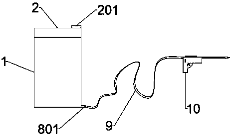
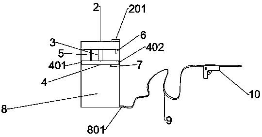
[0022] A grease filling device, comprising a main body 1, a battery 2 is installed on the upper part of the main body 1, the interior of the main body 1 is a cavity, and an electric telescopic rod 3 is installed on the top of the interior of the main body 1, and the electric telescopic rod 3 One end is fixedly connected to the upper cover of the main body 1, the other end of the electric telescopic rod 3 is fixedly connected to a movable cover 4, a distance sensor 5 is installed on the left side of the electric telescopic rod 3, and one end of the distance sensor 5 is fix...


PUM


Abstract

The invention discloses lubricating grease filling equipment. The lubricating grease filling equipment comprises a main body which is of a cylindrical barrel-shaped structure. The upper portion of themain body is provided with a storage battery. The main body is internally provided with a cavity. The upper portion inside the main body is provided with an electric extensible and retractable rod. One end of the electric extensible and retractable rod is arranged at the center position of an upper cover of the main body. The left side of the electric extensible and retractable rod is fixedly provided with a distance sensor. The other end of the distance sensor is arranged on the upper portion inside the main body. The right side of the electric extensible and retractable rod is provided witha control chip. The other end of the electric extensible and retractable rod is provided with a round movable cover. The periphery of the movable cover is provided with a groove. The groove is internally provided with a sealing ring. The lower end of the movable cover is provided with a pressure sensor. A storage chamber is arranged below the movable cover. The lower portion of the storage chamber is provided with an oil nozzle. The oil nozzle is connected with a wired hose, and the other end of the wired hose is provided with an oil gun. The lubricating grease filling equipment is simple instructure, easy to operate and convenient to maintain and use, and great popularization value is achieved.

Description

technical field [0001] The invention relates to the field of industrial repair and maintenance, in particular to a lubricating grease filling device. Background technique [0002] At present, the filling of lubricating grease is mainly done manually, and the lubricating grease is pressurized through the compressor through the principle of leverage, and injected into the equipment that needs to be filled with lubricating grease. However, this filling method is time-consuming and laborious. However, most of the lubricating grease filling equipment used in the lubrication system has a large structure and is not easy to carry, and the operation is cumbersome, and it is not easy to use and maintain. The main reason is that most of the grease filling equipment is not highly integrated, and the scattered structure and layout of multiple components is not reasonable, so it is not easy to carry and use, and when using the grease filling equipment, it is easy to appear Large, the phe...

Claims


Application Information

Patent Timeline
Patent Type & Authority Applications(China)
IPC IPC(8): F16N3/10F16N3/12F16N29/00
CPCF16N3/10F16N3/12F16N29/00
Inventor 王志勇潘海霞赵红霞潘鎏华尚杰顾环
Owner JIANGSU SHORTCUT DISABILITIES LUBRICANT
Why Eureka
Try Eureka