Efficient detector used for docking stations
A docking station and detector technology, which is applied in the direction of instruments, measuring electronics, measuring devices, etc., can solve the problems of easily damaged laptops, increased labor intensity, and prone to false detection, so as to avoid shaking or even shaking, and reduce labor costs. The effect of reducing intensity and reducing the probability of missed detection and false detection
- Summary
- Abstract
- Description
- Claims
- Application Information
AI Technical Summary
Problems solved by technology
Method used
Image

Examples
Embodiment 1
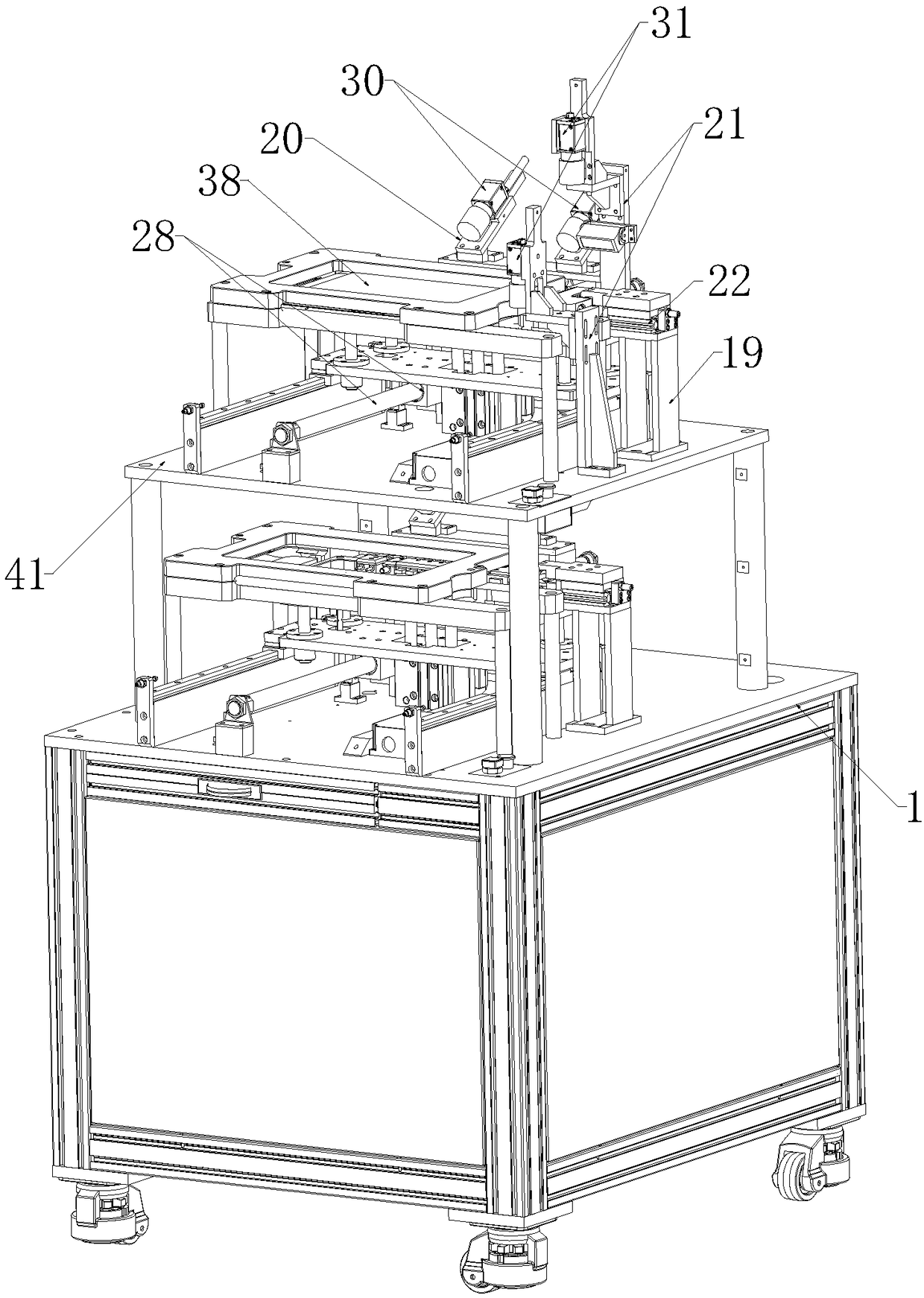
[0042] Such as Figure 1 to Figure 4 As shown, the high-efficiency detector for the docking station includes a base 1 and a partition frame 41 fixedly connected to the base 1. The partition frame 41 divides the space above the base 1 into an upper area and a lower area below the upper area. A first detection unit is set in the area, and a second detection unit is set in the lower area;
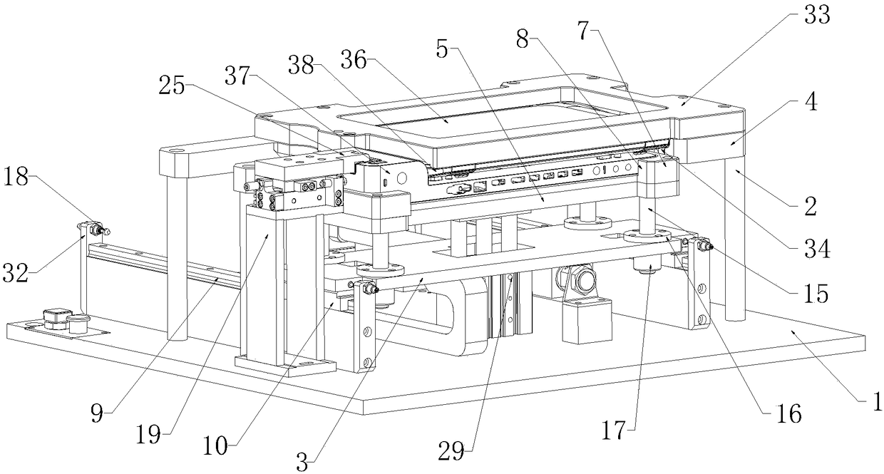
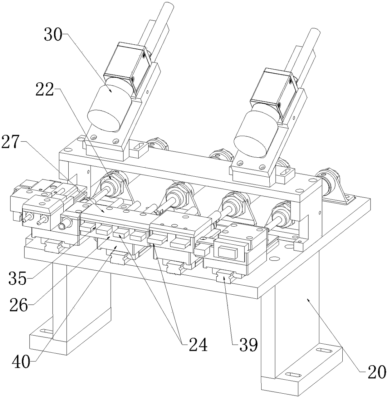
[0043] Both the first detection unit and the second detection unit include a first support frame 2, a first drive device, a second support frame connected to the output end of the first drive device, and a third support frame 19 on one side of the first support frame 2 , the fourth support frame 20 located at the rear end of the first support frame 2, the first driving device acts on the second support frame 3, so that: the second support frame 3 can move back and forth relative to the first support frame 2; The first positioning member is provided; the second support frame 3 is provided with...
Embodiment 2
[0048] This embodiment makes the following further limitations on the basis of Embodiment 1: the base 1 and the partition frame 41 are provided with two first guide rails 9 respectively located on both sides of the first driving device 28, and the second The lower end of the support frame 3 is provided with two first sliders 10 which can be slidably matched with the two first guide rails 9 respectively.
[0049] Preferably, the front and rear ends of the first guide rail 9 are provided with limiting plates 32 , and the limiting plates 32 are provided with buffer columns 18 that can act on the first slider 10 .
Embodiment 3
[0051] This embodiment makes the following further limitations on the basis of Embodiment 1: the second support frame 3 is provided with several guide cylinders 16 that run through its upper and lower end surfaces;
[0052] The lower end of the second positioning member 5 is provided with several guide rods 15 which can respectively pass through several guide cylinders 16 , and the guide rods 15 can move up and down relative to the guide cylinders 16 .
[0053] Preferably, the bottom end of the guide rod 15 is provided with a limit head 17 located below the second support frame 3. The width of limit head 17 should be greater than the opening width of guide cylinder 16 lower ends.
[0054] A first pressure sensor 13 is installed on the inner wall of the edge 7 of the second positioning member 5 on the side away from the third support frame 19;
[0055] A second pressure sensor 14 is installed on the inner wall of the edge 7 at the front end of the second positioning member 5 ....
PUM
 Abstract
Description
Claims
Application Information
 - R&D
- Intellectual Property
- Life Sciences
- Materials
- Tech Scout
- Unparalleled Data Quality
- Higher Quality Content
- 60% Fewer Hallucinations
Browse by: Latest US Patents, China's latest patents, Technical Efficacy Thesaurus, Application Domain, Technology Topic, Popular Technical Reports.
© 2025 PatSnap. All rights reserved.Legal|Privacy policy|Modern Slavery Act Transparency Statement|Sitemap|About US| Contact US: help@patsnap.com