A Compensation Method for Robot Bending Accuracy Based on Sheet Metal Tensile Deformation

A tensile deformation and precision compensation technology, applied in the direction of instruments, simulators, computer control, etc., can solve the problem of low bending accuracy of robots, and achieve the effect of eliminating pulling or squeezing and improving bending accuracy.

Active Publication Date: 2021-03-19
NANJING ESTUN ROBOTICS CO LTD
View PDF7 Cites 0 Cited by
  • Summary
  • Abstract
  • Description
  • Claims
  • Application Information

AI Technical Summary

Problems solved by technology

[0004] The technical problem to be solved by the present invention is to overcome the defects existing in the prior art, and propose a robot bending accuracy compensation method based on sheet metal tensile deformation, which solves the problems caused by sheet material tensile deformation during the bending process. The problem of low bending precision of robots, improve the bending precision of robots

Method used


Image

  • A Compensation Method for Robot Bending Accuracy Based on Sheet Metal Tensile Deformation
  • A Compensation Method for Robot Bending Accuracy Based on Sheet Metal Tensile Deformation
  • A Compensation Method for Robot Bending Accuracy Based on Sheet Metal Tensile Deformation

Examples


Embodiment Construction

[0045] The present invention will be specifically described in connection with the examples and drawings.

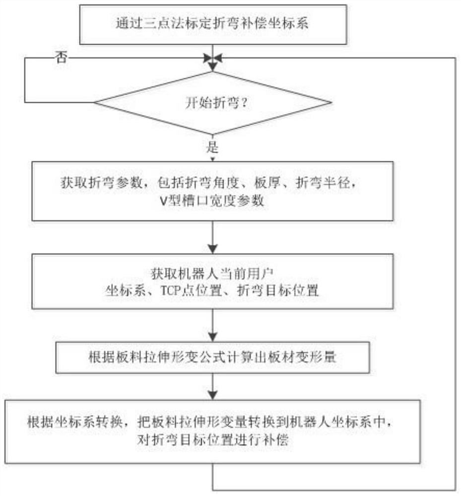
[0046] The implementation steps are as follows:

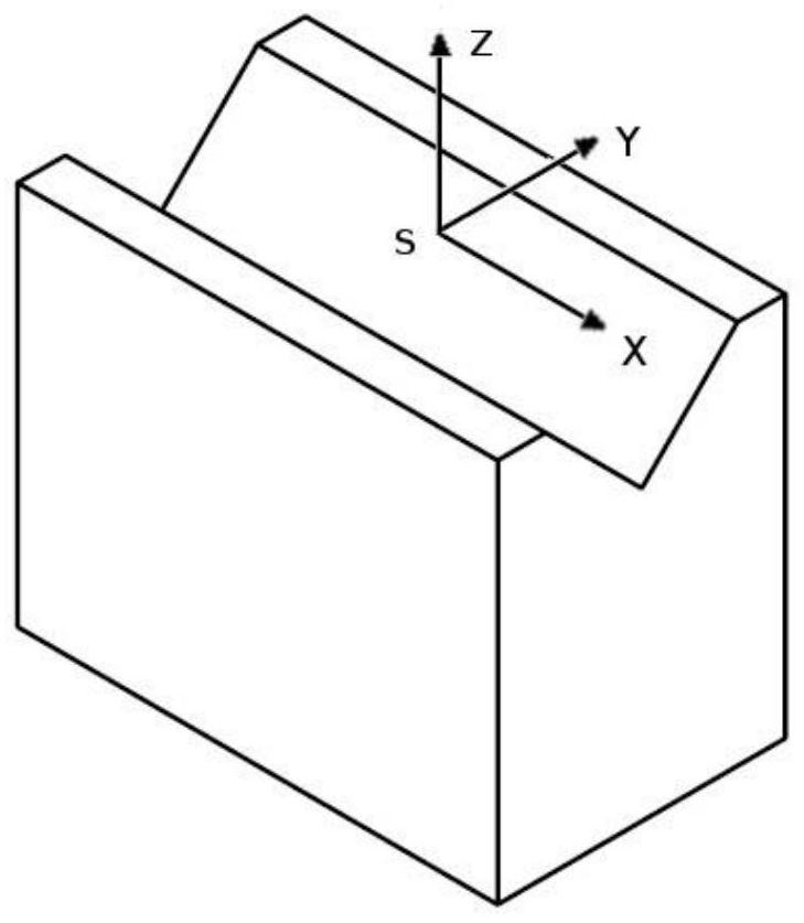
[0047] Step 1: Three points on the slot through the robot, the origin O coordinate value is P O (1896.72, -239.85, 1033.50), point P in the X-axis direction of the compensation coordinate system in the inlet direction A (1835.10, -1672.77, 1038.03), calibration compensation coordinate system xy flat direction point P B (1856.89, -1437.79, 1037.22), the X, Y, Z-axis unit vector of the compensation coordinate system is obtained, respectively, and the rotation matrix is ​​as follows:

[0048]

[0049] According to the Z-Y-Z ELA conversion formula, by the rotary matrix R S The A = -92.46, b = 0, c = 0, thereby obtaining the compensation coordinate system as follows:

[0050] S = (1896.72, -239.85, 1033.50, -92.46, 0)

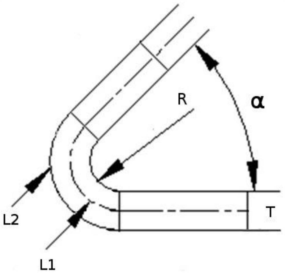
[0051] Step 2: Get the bending parameters, bending the angle α = 90o, the bend radius R = 1 mm, the plate thic...


PUM


Abstract

The invention discloses a board tensile deformation based robot bending precision compensating method. First, a compensation coordinate system S is established in a V-shaped notch of a bending machine; bending parameters set by a user are acquired; after bending tracking is started, a user coordinate system CS (X, Y, Z, A, B, C) of a current robot system and robot TCP position P1 (X, Y, Z, A, B, C) are acquired and a bending target position P2 (X, Y, Z, A, B, C) is acquired; board tensile deformation during the board bending process is calculated and compensation of a compensation coordinate system S' is converted to be in the user coordinate system CS and is then compensated to the position P2, so that the new target position P2' subjected to compensation is acquired. According to the invention, board tensile deformation generated in a bending process is taken into account fully and board deformation is compensated to the target position tracked by the robot, pulling or extrusion on the board by the robot during the bending tracking process is eliminated and the bending precision is improved.

Description

Technical field [0001] The present invention relates to a bent industrial robot, specifically a method involving bending robot bent precision compensation. Background technique [0002] With the continuous reduction in labor resources and the continuous improvement of labor costs, the demand for robot bending applications is increasingly urgent. At present, the accuracy of the robot has been satisfied, but the sheet is generated during the bending process, causing the robot to pull or extrusion of the sheet after the bending, affect the bending accuracy. [0003] Chinese invention patent application "robot bend real-time follow-up method and device" (CN10475504A) A method of bending real-time followed by an external detecting device pre-acquired a bending cutter displacement amount within a specific period, then According to the displacement of the bending knife, the position of the end of the robot is calculated, and the robot bends realistic to follow effect. This method only c...

Claims


Application Information

Patent Timeline
Patent Type & Authority Patents(China)
IPC IPC(8): G05B19/404
CPCG05B19/404G05B2219/35362
Inventor 宋方方敬淑义王杰高
Owner NANJING ESTUN ROBOTICS CO LTD
Why Eureka
Try Eureka