
Mixer, Vacuum Treatment Unit

A technology of mixer and mixing container, which is applied in the direction of mixer, mixing method, gas and gas/steam mixing, etc., and can solve problems such as difficult to increase TEOS gas flow rate

Active Publication Date: 2020-03-20
ULVAC INC
View PDF10 Cites 0 Cited by
  • Summary
  • Abstract
  • Description
  • Claims
  • Application Information

AI Technical Summary

Problems solved by technology

[0011] In general, since it is difficult to secure a vapor pressure of 2600 Pa or more in liquid TEOS, the pressure difference between the pressure at the place where TEOS gas is generated and the pressure in the mixing vessel becomes small, so it is possible to easily increase the high pressure and fill the gas Oxygen flow of high pressure tank, but difficult to increase the flow of TEOS gas

Method used


Image

  • Mixer, Vacuum Treatment Unit
  • Mixer, Vacuum Treatment Unit
  • Mixer, Vacuum Treatment Unit

Examples


no. 3 example 〉

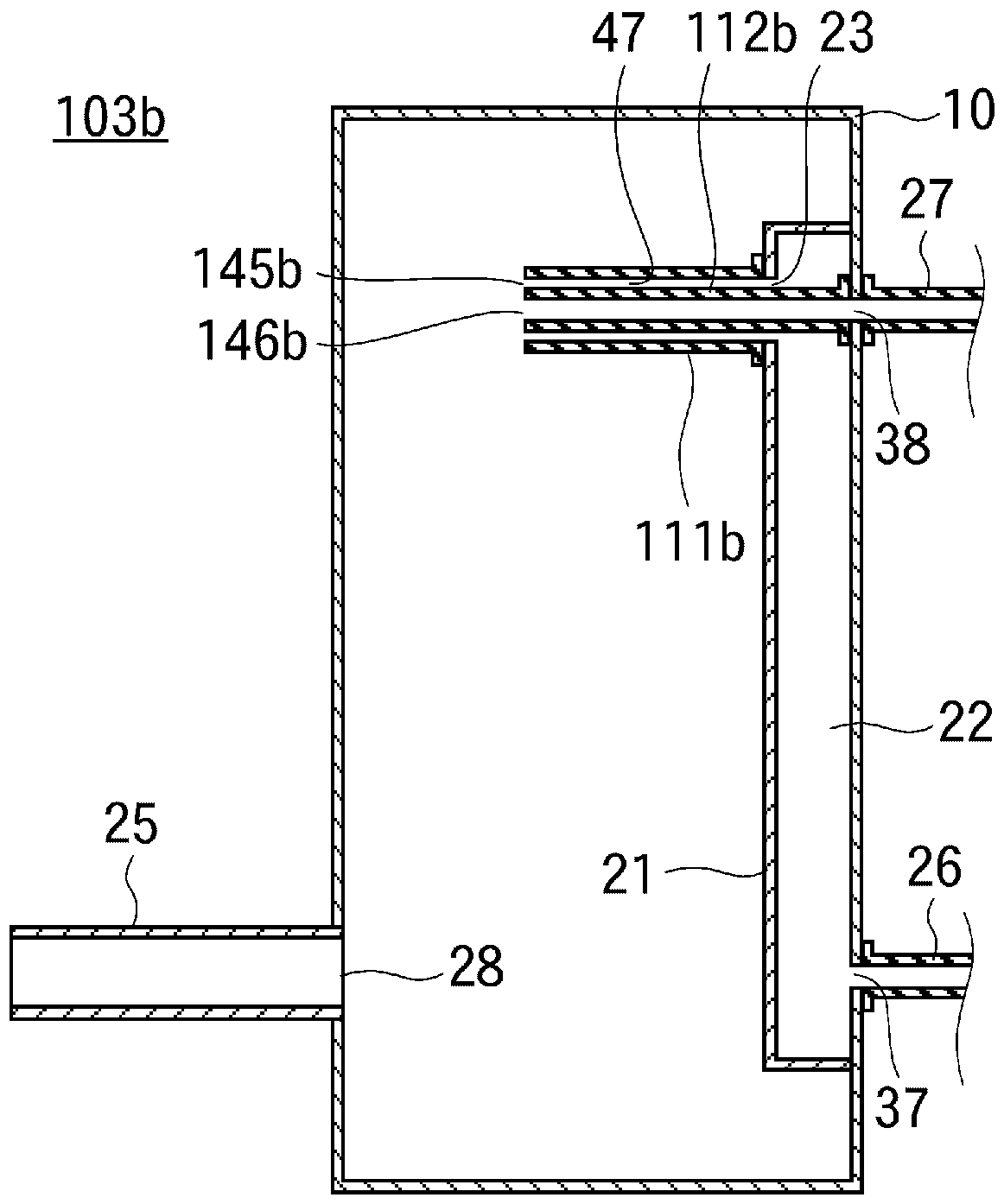
[0122] In the mixers 3 and 3a described above, the first gas is introduced into the small chamber 21 provided inside the mixing container 10, and the first gas in the small chamber 21 is moved to the gap 47, but as Figure 4 Like the mixer 3b of the third embodiment shown, the small chamber 21 may not be provided, but the gap 47 may also be formed outside the mixing container 10, and the first gas may be introduced into the gap 47 outside the mixing container 10.

[0123] Although the first and second cylinder openings 45b and 46b of the first and second cylinder main bodies 11b and 12b at this time are disposed inside the mixing container 10, the gap 47 is also formed outside the mixing container 10. The second cylinder main bodies 11 b and 12 b also include a portion forming a gap 47 outside the mixing container 10 .

no. 4 example 〉

[0125] Like the mixer 3b of the above-mentioned third embodiment, when the first and second barrel bodies 11b, 12b also extend outside the mixing container 10, as Figure 5 Like the mixer 3c of the fourth embodiment, the first cylinder main body 11c may be located inside and outside the mixing container 10, the first cylinder opening 45c may be located inside the mixing container 10, and on the other hand, the second cylinder main body 12c is inserted into the portion outside the first cartridge main body 11c so that the second cartridge opening 46c is located at the same position as the wall of the mixing container 10 or outside the wall of the mixing container 10 .

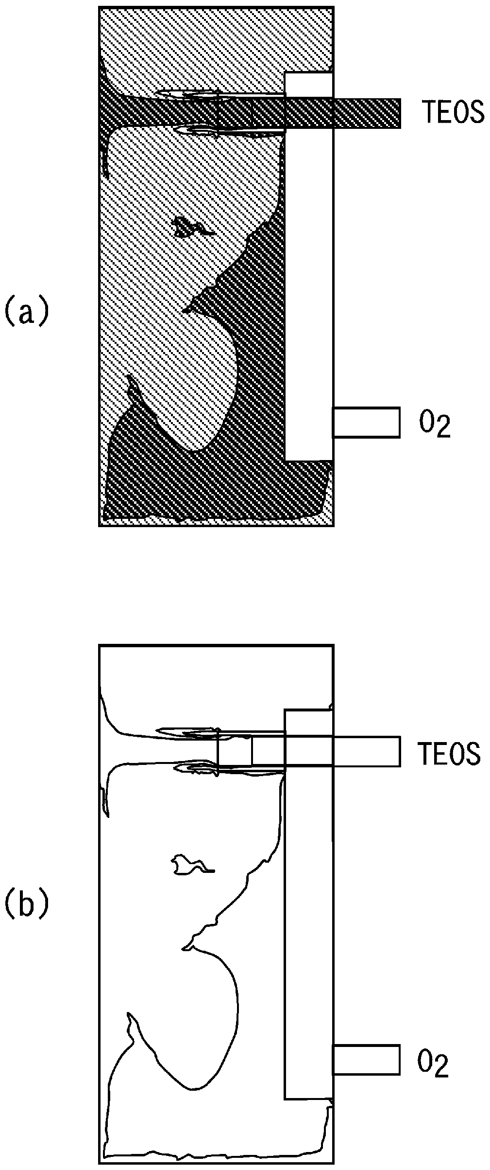
[0126] The mass fraction distribution of this mixer 3c is as Figure 14 shown. The first gas is TEOS gas, and the second gas is oxygen (introduction example 1). Since the first cylinder opening 45c is located in the range of 2 / 5 to 3 / 5, good mixing and uniform mixing can be achieved.

no. 5 example 〉

[0128] In the mixers 3, 3a to 3c of the first to fourth embodiments, the outflow ports 28, 28a are provided outside the portion 14 where the virtual cylinder 29 intersects with the wall surface of the mixing container 10, but Figure 6 The mixer 3d of the fifth embodiment is that the outflow port 28 is in figure 2 In the mixer 3 of the first embodiment, it is arranged so as to completely or at least partially overlap the intersection portion 14 such that the outer peripheral side surface of the first cylinder main body 11d is virtual in the direction in which the first cylinder main body 11d extends. The wall surface of the portion where the extended virtual cylinder 29 intersects with the wall surface of the mixing container 10 .

[0129] In addition, in the mixer 3d of the fifth embodiment, the baffle member 44 is disposed between the first cylinder opening 45d and the outflow port 28 .

[0130] The baffle member 44 is located between the first cartridge opening 45d and th...


PUM


Abstract

Provided are a mixer for uniformly mixing a first gas and a second gas, and a vacuum processing apparatus using the mixer. The second cylinder main body (12) is arranged inside the first cylinder main body (11) in a non-contact manner with the second cylinder opening (46) located in the first cylinder main body (11), and the first cylinder main body (11) A run-up space (48) is formed between the first tube opening (45) and the second tube opening (46) inside, so that the second gas flows out from the second tube opening (46) to the run-up space (48), so that The first gas flows out from the gap (47) formed between the first and second barrel bodies (11, 12) to the run-up space (48), so that the first and second gases are surrounded by the first gas when the second gas In the state, it flows to the run-up space (48), so that it flows out from the first barrel opening (45) to the mixing container (10). The first and second gases travel straight in the mixing container (10), collide with the wall of the mixing container (10) facing the opening of the first cylinder (45), form the vortex of the first and second gases, and are supplied to the mixing container (10). Even if the difference between the flow rates of the first and second gases in the container (10) is large, they are uniformly mixed.

Description

technical field [0001] The present invention relates to the technical field of a gas mixer and a vacuum processing device using the mixer. Background technique [0002] In order to mix different types of gases, the different types of gases flowing in the two pipes are combined and flow into one pipe with a bend. When the two gases flow in the bend, they are separated by the vortex generated in the bend. Mix two gases. [0003] Although this hybrid method has a simple shape and can be realized at low cost, it causes a large pressure loss at the bent portion. [0004] In particular, when the pressure of one gas source of the two gases is high and the pressure of the other gas source is low, the amount of gas supplied from the low-pressure gas source decreases due to pressure loss, and the gas flow rate ratio changes from a desired value. Deviate. [0005] Especially in the following cases, if the supply amount of the raw material substance of the gas is reduced, the growth ...

Claims


Application Information

Patent Timeline
Patent Type & Authority Patents(China)
IPC IPC(8): C23C16/455B01F3/02H01L21/31B01F23/10
CPCC23C16/455H01L21/31B01F23/10C23C16/402C23C16/45512B01F23/19B01F35/50
Inventor 田宫慎太郎神保洋介阿部洋一
Owner ULVAC INC
Learn More