Honeycomb plate feeding device

A technology of honeycomb panels and guide rails, which is applied in the field of honeycomb panel feeding devices, and can solve problems such as inability to install honeycomb panels, low efficiency, and labor-intensive

Inactive Publication Date: 2018-06-12
WUXI CHANGZHISHENG MACHINERY MFG CO LTD
View PDF8 Cites 7 Cited by
  • Summary
  • Abstract
  • Description
  • Claims
  • Application Information

AI Technical Summary

Problems solved by technology

[0002] Honeycomb panels usually include upper and lower panels and a honeycomb core in the middle. During production, these components need to be assembled together to realize the production of honeycomb panels. The first step in assembling these components is to first process the honeycomb panels. The components are tran

Method used


Image

  • Honeycomb plate feeding device

Examples


Embodiment Construction

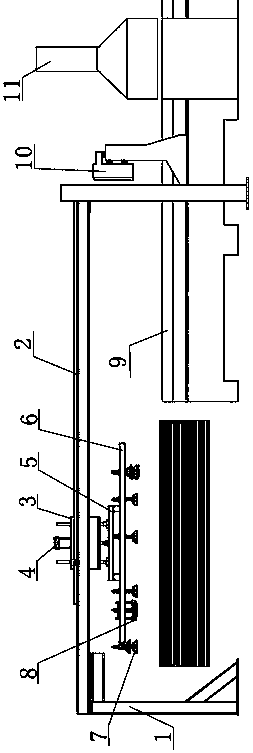
[0009] Such as figure 1 The honeycomb sheet material device shown includes a bracket 1, a guide rail 2, a moving block 3 is installed on the guide rail 2, a lifting column 4 is installed on the moving block 3, a fixing frame 5 is connected to the bottom of the lifting column 4, and the bottom of the fixing frame 5 A suction cup holder 6 is installed. The size of the suction cup holder 6 corresponds to the size of the honeycomb panel component being transported. The suction cup holder 6 is equipped with a rubber disk 7 through a connecting rod and a spring, and the suction cup holder 6 is also installed with a connecting rod and spring. Pressure sensor 8; under one end of the guide rail 2, there is a roller conveyor 9, and the roller conveyor 9 is sequentially installed with a proximity sensor 10, a vacuum cleaner 11, a pressure sensor 8, a lifting column 4, a guide rail 2, a proximity sensor 10 and a vacuum cleaner 11 Connect with the controller electric control.

[0010] When i...


PUM


Abstract

The invention provides a honeycomb plate feeding device, which can be used for transferring a honeycomb plate assembly to be processed to a production device, is free from consuming manpower, is highin efficiency, and can be further used for dedusting the honeycomb plate assembly. The invention has the technical scheme that the honeycomb plate feeding device comprises a support and a guide rail,wherein a movable block is arranged on the guide rail; a lifting stand column is arranged on the movable block; a fixing frame is connected to the bottom part of the lifting stand column; a sucker frame is arranged on the bottom part of the fixing frame; the size of the sucker frame corresponds the size of the honeycomb plate to be conveyed; plastic plates are arranged on the sucker frame throughconnecting rods; a pressure sensor is further arranged on the sucker frame through a connecting rod; a roller conveyor is arranged under one end of the guide rail; a proximity sensor and a dust collector are sequentially arranged on the roller conveyor; and the pressure sensor, the lifting stand column, the guide rail, the proximity sensor and the dust collector are in electronic control connection with the controller.

Description

Technical field [0001] The invention relates to the technical field of feeding devices, in particular to honeycomb board feeding devices. Background technique [0002] Honeycomb panels usually include upper and lower panels and a honeycomb core in the middle. These parts need to be assembled together during production to realize the production of honeycomb panels. The first step in assembling these parts is to assemble the honeycomb panels to be processed. The components are transferred to the production device, and the traditional method is to manually place the components on the production line, which not only consumes a lot of manpower but also has low efficiency; in addition, if the honeycomb panel components are too dusty and other impurities, the honeycomb panel cannot be installed. Summary of the invention [0003] In view of the above-mentioned problems, the present invention provides a honeycomb panel material device, which can transfer the honeycomb panel components to b...

Claims


Application Information

Patent Timeline
IPC IPC(8): B65G47/91
CPCB65G47/912
Inventor 吴坚
Owner WUXI CHANGZHISHENG MACHINERY MFG CO LTD
Why Eureka
Try Eureka