Eureka AIR delivers breakthrough ideas for toughest innovation challenges, trusted by R&D personnel around the world.

Fabricated open caisson wall cutting edge structure

A prefabricated shaft wall technology, which is applied in infrastructure engineering, caissons, buildings, etc., can solve the problems of large engineering volume, reduced subsidence coefficient, and small tensile area, and achieves good economy, convenient construction, and reasonable effect

Pending Publication Date: 2018-06-12
CCCC SHEC FOURTH ENG +2
View PDF9 Cites 1 Cited by
  • Summary
  • Abstract
  • Description
  • Claims
  • Application Information

AI Technical Summary

Problems solved by technology

Since the caisson mainly bears the vertical bending moment caused by its own weight during the sinking process, the bottom of the caisson is under tension. If a wedge-shaped structure is used, the tension area is small, and the bottom needs to be partially strengthened, which will increase the engineering amount.
[0005] 2. Considering the force on the well wall, the blade foot is made into a wedge shape, but still retains a certain width; at the same time, in order to ensure that the sand is found during the sinking of the caisson, a large amount of external soil will pour into the well, which will affect the structural safety and posture stability. feet into the soil to a certain depth
As a result, the well wall has a large supporting area during the sinking process of the caisson, which reduces the sinking coefficient and causes certain difficulties in sinking.
[0006] Therefore, the current caisson foundation edge structure has certain defects in economy, construction convenience or force rationality

Method used


Image

  • Fabricated open caisson wall cutting edge structure
  • Fabricated open caisson wall cutting edge structure

Examples


Embodiment Construction

[0020] The present invention will be further described below in combination with specific embodiments and accompanying drawings.

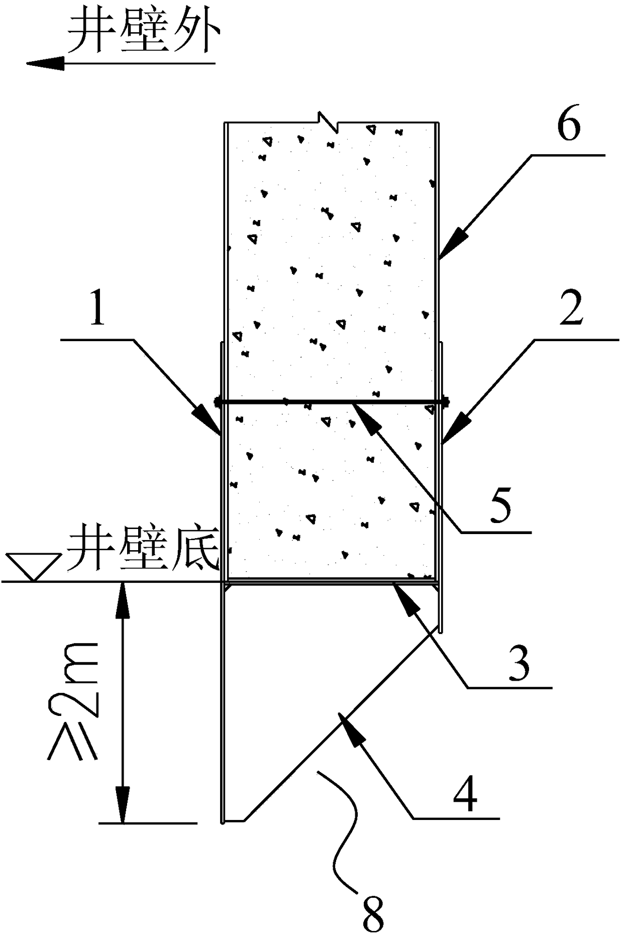
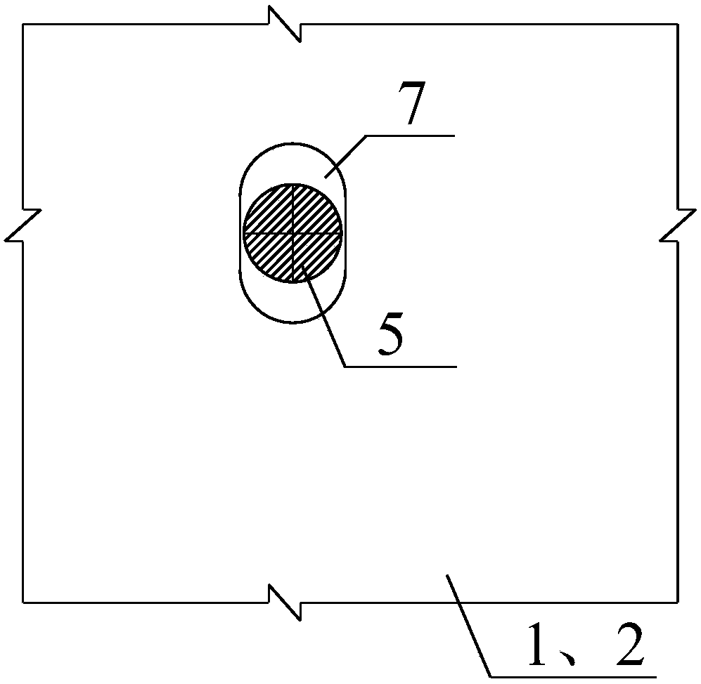
[0021] refer to figure 1 As shown, an assembled caisson wall blade foot structure, the shaft wall blade foot includes an outer vertical plate 1, an inner vertical plate 2, a horizontal plate 3 and a stiffening plate 4 connected as a whole, and the shaft wall blade foot passes through the The pulling screw 5 is assembled on the well wall 6 of the caisson; the outer vertical plate 1 is attached to the outer side of the well wall 6, the inner vertical plate 2 is attached to the inner side of the well wall 6, the horizontal plate 3 is attached to the bottom of the well wall 6, and the outer vertical plate 1 and the inner vertical plate 2 are hinged to the well wall 6 through the pull screw 5 passing through the well wall 6, the outer vertical plate 1 and the inner vertical plate 2 both protrude below the bottom of the well wall 6, and the outer vertica...


PUM


Abstract

The invention discloses a fabricated open caisson wall cutting edge structure and belongs to the field of bridge foundations. An open caisson wall cutting edge comprises an outer side vertical plate,an inner side vertical plate, a horizontal plate and a stiffening plate which are connected into a whole. The open caisson wall cutting edge is fabricated to an open caisson wall through a split bolt.The outer side vertical plate is attached to the outer side of the open caisson wall. The inner side vertical plate is attached to the inner side of the open caisson wall. The horizontal plate is attached to the bottom of the open caisson wall. The outer side vertical plate and the inner side vertical plate are hinged to the open caisson wall through the split bolt penetrating through the open caisson wall, and stretch below the bottom of the open caisson wall, and the outer side vertical plate is longer than the inner side vertical plate. The stiffening plate in a right triangle shape is located below the horizontal plate and perpendicularly connected with the outer side vertical plate, the inner side vertical plate and the horizontal plate. The stiffening plate, the outer side verticalplate, the inner side vertical plate and the horizontal plate define the edge tip of the open caisson wall cutting edge of a right-triangle-shaped fracture surface structure. The fabricated open caisson wall cutting edge structure is a novel open caisson wall cutting edge structure which is reasonable in stress, good in economical efficiency and convenient to construct.

Description

technical field [0001] The invention belongs to the field of bridge foundations, including deep water foundations and land foundations. Background technique [0002] With the development of domestic bridge construction, large-scale bridge foundations continue to appear. At present, the common bridge foundations mainly include pile foundations, enlarged foundations, and caisson foundations. Expanded foundations are greatly affected by geological conditions, and are less used in thicker covering layers or deep water; pile foundations are the most widely used, but for large bridge foundations, the scale of pile foundations is larger and the engineering cost is higher; while the stiffness of caisson foundations It is large and has good integrity, and has a large room for development in bridge construction. [0003] The current caisson foundation blade foot and shaft wall are integrated. In order to ensure the smooth sinking of the caisson and reduce the frontal soil resistance...

Claims


Application Information

Patent Timeline
Patent Type & Authority Applications(China)
IPC IPC(8): E02D23/00
CPCE02D23/00
Inventor 史良洪韦庆冬李冰甄宗标冯传宝汪成龙潘桂林魏湛力
Owner CCCC SHEC FOURTH ENG
Why Eureka
Eureka Blog
Learn More