Light shield for optical remote sensor

An optical remote sensor and hood technology, applied in the direction of the casing of the measuring device, etc., can solve the problem of reducing the thermal disturbance of the optical system caused by the incident sunlight, achieve good stray light suppression and heat dissipation effects, avoid direct sunlight, and weaken the thermal disturbance. Effect

Active Publication Date: 2018-06-12
CHANGCHUN INST OF OPTICS FINE MECHANICS & PHYSICS CHINESE ACAD OF SCI
View PDF7 Cites 6 Cited by
  • Summary
  • Abstract
  • Description
  • Claims
  • Application Information

AI Technical Summary

Problems solved by technology

[0004] The present invention aims to overcome the technical defect that the existing shading hood cannot prevent the energy incident into the shading hood from still causing strong thermal disturbance to the optical system, and provides a device that can greatly reduce the thermal disturbance of the optical system caused by incident sunlight and avoid direct sunlight. At the same time, the optical remote sensor hood that achieves good stray light suppression and heat dissipation effect

Method used


Image

  • Light shield for optical remote sensor
  • Light shield for optical remote sensor
  • Light shield for optical remote sensor

Examples


Embodiment Construction

[0031] In order to make the object, technical solution and advantages of the present invention clearer, the present invention will be further described in detail below in conjunction with the accompanying drawings and specific embodiments. It should be understood that the specific embodiments described here are only used to explain the present invention, but not to limit the present invention.

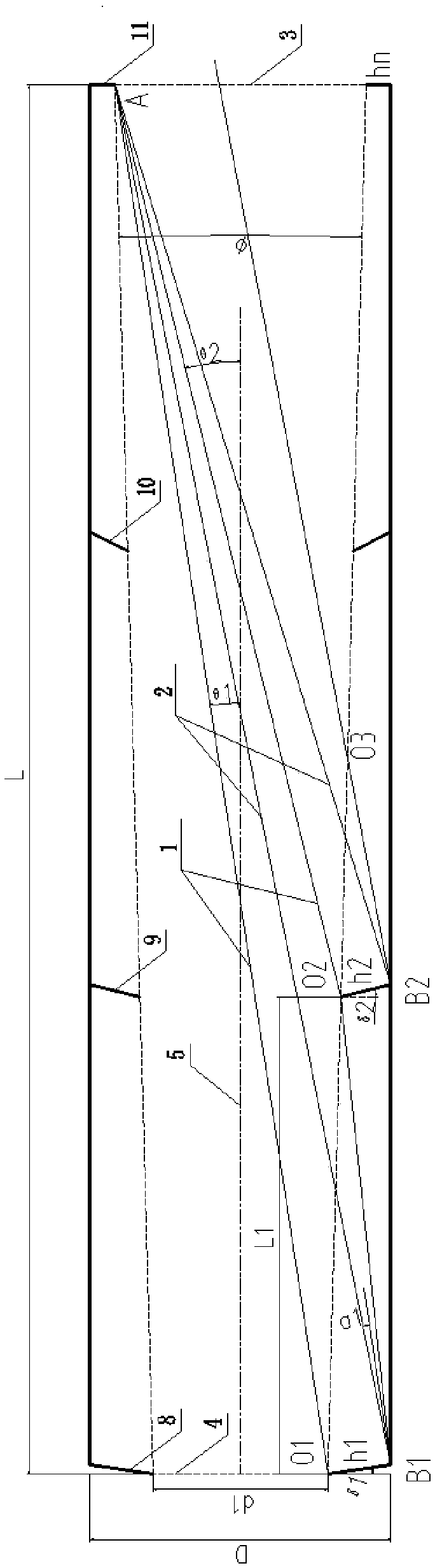
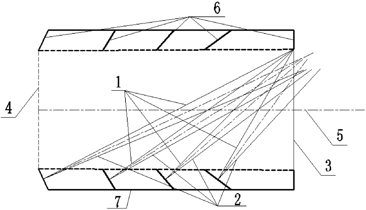
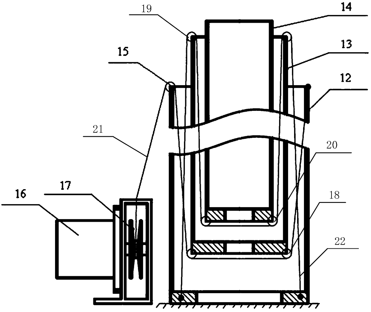
[0032] first reference Figure 1 to Figure 5 , shows an optical remote sensor light shield according to an embodiment of the present invention, which is an on-orbit deployable light shield suitable for an optical remote sensor in a geostationary orbit. The light shield is a passive light shield, that is, the configuration remains unchanged after the rail is deployed, which can significantly improve the thermal performance of the optical system.

[0033] The optical remote sensor shading cover includes a light blocking ring assembly, a stretching mechanism, a driving mechanism and an a...


PUM


Abstract

The invention relates to the technical field of sun shielding for a light inlet of a high-orbit space optical remote sensor, and specifically relates to a light shield for an optical remote sensor. The light shield comprises a light blocking ring assembly, an extension mechanism, a driving mechanism and an annular flexible wall. The light shield for the optical remote sensor is in a compressed state before a satellite enters the orbit, the walls of all stages of light blocking rings are in a folded state, the extension mechanism is unfolded stage by stage under the driving of the driving mechanism after the satellite enters the predetermined orbit, the extension mechanism drives the corresponding light blocking rings to be unfolded stage by stage, the walls between the light blocking ringsare unfolded accordingly, and thus the whole light shield for the optical remote sensor is gradually unfolded in orbit along the direction of an optical axis of a camera. The light shield can directly reflect the incident sunlight after being unfolded in orbit, can directly reflects part of the incident light out of the light shield, and can also move part of the incident light forward, thereby significantly weakening the thermal disturbance imposed on an optical system by the incident sunlight, and achieving good effects of stray light suppression and heat dissipation while avoiding the direct sunlight.

Description

technical field [0001] The invention relates to the technical field of sun shading at light inlets of high-orbit space optical remote sensors, in particular to a light shading cover for optical remote sensors. Background technique [0002] The optical remote sensor in geostationary orbit has the remarkable characteristics of wide visual range, long monitoring time, and fixed-point timing camera. In theory, it can cover most of the world's regions through a three-satellite network. All-weather survey capability. Due to the huge application prospects of high-orbit optical remote sensors in the fields of weather forecasting, environmental protection, and land survey, the development of high-orbit optical remote sensors has been started at home and abroad. For space optical remote sensors in geostationary orbit, it faces In the complex and alternating heat flow outside the space, the light entrance of the camera will be directly irradiated by the sun during nearly half of the o...

Claims


Application Information

Patent Timeline
IPC IPC(8): G01D11/24
Inventor 关奉伟曹乃亮赵庆磊关洪宇刘巨
Owner CHANGCHUN INST OF OPTICS FINE MECHANICS & PHYSICS CHINESE ACAD OF SCI
Why Eureka
Try Eureka