Defect location method for t-shaped stringers based on ultrasonic guided waves

A technology of ultrasonic guided wave and positioning method, which is applied in the use of sound wave/ultrasonic wave/infrasonic wave to analyze solids, use sound wave/ultrasonic wave/infrasonic wave to analyze materials, and instruments, etc. It can solve the difficulty of increasing detection, long detection time, high cost, etc. problem, achieve the effect of realizing longitudinal defect positioning, accurate longitudinal defect positioning, and realizing horizontal defect position discrimination

Active Publication Date: 2020-06-02
DALIAN UNIV OF TECH
View PDF6 Cites 0 Cited by
  • Summary
  • Abstract
  • Description
  • Claims
  • Application Information

AI Technical Summary

Problems solved by technology

At present, a variety of detection technologies can theoretically be used for the defect location of stringer structures, but the traditional point-by-point scanning method takes a long time and costs a lot
In addition, most of the stringer structures are arranged in invisible aircraft structures that are difficult to operate in a wide range, which increases the difficulty of detection

Method used


Image

  • Defect location method for t-shaped stringers based on ultrasonic guided waves
  • Defect location method for t-shaped stringers based on ultrasonic guided waves
  • Defect location method for t-shaped stringers based on ultrasonic guided waves

Examples


Embodiment Construction

[0024] In order to make the technical solutions and advantages of the present invention more clear, the technical solutions in the embodiments of the present invention are clearly and completely described below in conjunction with the drawings in the embodiments of the present invention:

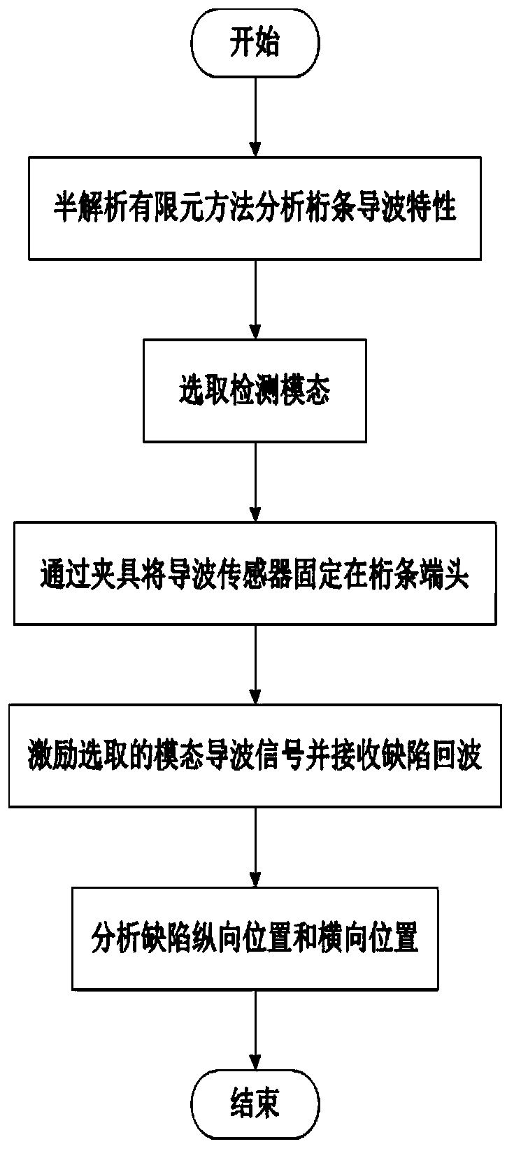
[0025] Such as figure 1 The shown T-shaped stringer defect location method based on ultrasonic guided waves specifically includes the following steps:

[0026] S1: According to the T-shaped stringer cross-sectional size, material density, elastic modulus, and Poisson's ratio information, the guided wave characteristics propagating on the T-shaped stringer are obtained through theoretical analysis by the semi-analytical finite element method. The guided wave characteristics include dispersion curve and wave structures;

[0027] S2: Select each frequency and mode for detection through the dispersion curve and wave structure, and according to the different sensitive modes corresponding to diff...


PUM

PropertyMeasurementUnit
lengthaaaaaaaaaa
thicknessaaaaaaaaaa
densityaaaaaaaaaa

Abstract

The invention discloses a method for positioning defects of a T-type stringer on the basis of ultrasonic guided waves. The method comprises the following specific steps of: (S1) analyzing by the semi-analytical finite element method theory to obtain a guided-wave characteristic propagating on the T-type stringer; (S2) selecting all frequencies and modes for detection by frequency dispersion curvesand wave structures; (S3) carrying out excitation and reception of guided waves on the ends of the T-type stringer along guided-wave sensors arranged along the circumferential direction, wherein thesensors are fixed by clamps and are coupled with the surface of the stringer; (S4) using signal excitation equipment to generate guided-wave signals with the selected frequencies; (S5) determining longitudinal positions of the damages by time difference between peak values of echo signals and excitation signals according to the excitation frequency and the mode wave velocity selected every time, and determining positions of horizontal defects according to detection results of all frequencies and modes with different horizontal-defect sensitivity.

Description

technical field [0001] The invention relates to the field of stringer non-destructive testing, in particular to a T-shaped stringer defect location method based on ultrasonic guided waves. Background technique [0002] Stringer structures are widely used in various aerospace vehicle structures, such as aircraft wings, fuselages and rocket bodies. The stringer structure plays the role of supporting the skin in the aircraft, and bears axial tension and compression, bending, shearing and torsional loads caused by gravity, thrust, aerodynamic resistance, etc., and may also bear stress and fatigue loads caused by low temperature. Complicated load conditions are very likely to cause defects in the stringers, and the defects will affect the reliability of the stringers, and even cause the structure of the stringers to break, leading to the failure of the aircraft structure. [0003] On November 5, 2010, NASA announced that the launch mission of the Discovery space shuttle STS-133 ...

Claims


Application Information

Patent Timeline
Patent Type & Authority Patents(China)
IPC IPC(8): G01N29/04
CPCG01N29/041G01N2291/0234
Inventor 武湛君张佳奇杨正岩刘科海郑跃滨周凯马书义高东岳
Owner DALIAN UNIV OF TECH
Why Eureka
Try Eureka