
A Fault Traveling Wave Filtering Method Based on Feature Point Identification and Linear Interpolation
A linear interpolation, fault traveling wave technology, applied in the field of power system, can solve the problems of inability to overcome the calculation error of signal fluctuation, not effectively eliminating noise fluctuation, etc., to achieve the effect of strong purpose, good filtering effect, and eliminating fluctuation interference.
- Summary
- Abstract
- Description
- Claims
- Application Information
AI Technical Summary
Problems solved by technology
Method used
Image


Examples
Embodiment Construction
[0032] The present invention will be described in further detail below in conjunction with the accompanying drawings and embodiments.
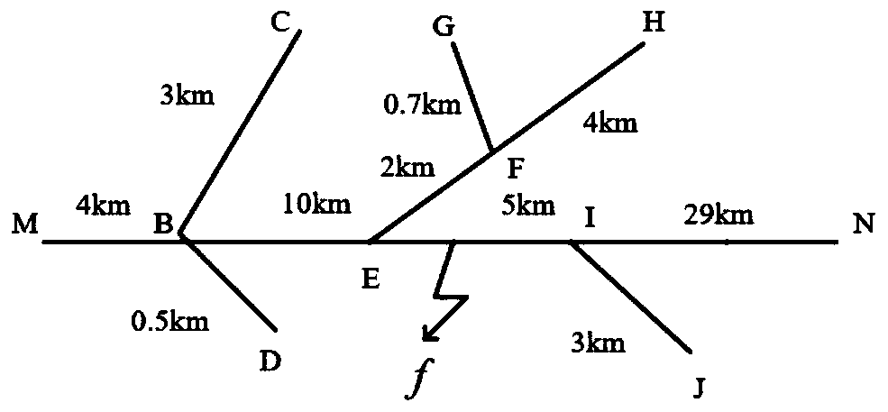
[0033] like figure 1 As shown, an actual 10kv distribution network structure schematic diagram is given. When a single-phase ground fault occurs, the fault location method proposed by the present invention is used.
[0034] Among them, point M represents the power supply side of the distribution network, and N represents the end of the line. Points M and N are equipped with voltage transformers and measuring devices, which are used to collect voltage traveling wave signals after faults. C, D, G, H, J, N represent the branch ends, and the three-phase unbalanced load is connected through the transformer. All the lines are overhead bare conductors, and the frequency-varying parameter model is adopted. The length of each line is as follows: figure 1 shown.
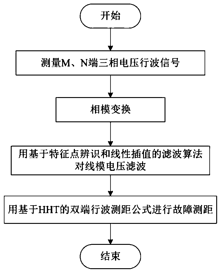
[0035] like figure 2 As shown, a fault traveling wave filtering method based on feat...
PUM
 Abstract
Description
Claims
Application Information