
Target tracking method with self-restoration capacity based on multi-stage detector

A target tracking and detector technology, which is applied to instruments, image data processing, character and pattern recognition, etc., can solve the problems of decreased detection target accuracy, affected tracking effect, tracking error, etc., to achieve high engineering application value and improve tracking performance. , the effect of improving the accuracy

Active Publication Date: 2018-06-12
BEIHANG UNIV
View PDF3 Cites 11 Cited by
  • Summary
  • Abstract
  • Description
  • Claims
  • Application Information

AI Technical Summary

Problems solved by technology

However, in the actual process of using detection to track the target, the common problem of the above algorithms is the tracking error caused by various possible factors. During the tracking process, the error gradually accumulates, which will lead to the decline in the accuracy of the subsequent detection target, and finally Affect Tracking Effect
In addition, in the initialization stage of target tracking, the acquired target initial template itself has accuracy problems, which will seriously affect the accuracy of the subsequent tracking process.
If there are obstacles or buildings in the trajectory of the target's movement, the target's features will disappear partially or even completely due to being blocked. When the target reappears, it will not be able to re-detect and continue tracking

Method used


Image

  • Target tracking method with self-restoration capacity based on multi-stage detector
  • Target tracking method with self-restoration capacity based on multi-stage detector
  • Target tracking method with self-restoration capacity based on multi-stage detector

Examples


Embodiment Construction

[0065] The present invention will be described in detail below in conjunction with the accompanying drawings and embodiments.

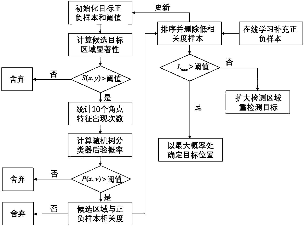
[0066] Such as figure 1 Shown, the concrete realization steps of the present invention are as follows:

[0067] (1) Build a saliency detector

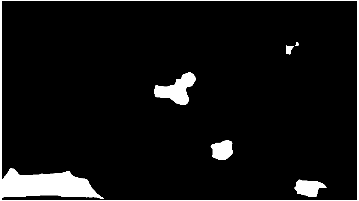
[0068] After initializing the first frame of image, determine the location of the target and the size of the area, and superimpose appropriate Gaussian noise and rotation transformation on the image block where the target is located, generate a series of positive sample sets of the target, and then randomly collect several such samples in the area outside the target. Large background image patches, as a set of negative samples. When the following image frames are input, the salient regions in the image are first detected by a saliency detector.

[0069] The principle of the saliency detector is to calculate the Euclidean distance between each pixel and the average brightness value of all pixels in the entir...


PUM


Abstract

A target tracking method with self-restoration capacity based on a multi-stage detector includes the steps of selecting a plurality of detectors of different types to be connected in series in combination with the concept of cascading Adaboost multi-stage weak classifiers into a strong classifier, selecting a significance detector for first-stage detection, selecting a classifier assembly detecting module for second-stage detection, substituting the classifier assembly detecting module into a random tree to calculate the posterior probability of a positive sample in a probable area detected byfirst-stage detection, selecting a related filtering detector for third-stage detection, calculating the relevance between a sample with the posterior probability larger than a certain threshold andthe positive sample initialized or obtained in the last frame so as to reduce accumulated errors caused by long-term tracking, determining the position with the maximum relevance as the target area inthe current frame through the multi-stage detector, sampling the determined position, supplementing the positive and negative sample number of concentrated removed samples to ensure the reliability and number consistency of the samples, activating a redetection mechanism if the maximum value of the relevance is larger than a certain threshold, and detecting the area near the position again to search for a target.

Description

technical field [0001] The present invention designs a target tracking method with self-recovery capability based on multi-level detectors, and connects multiple detectors of different types in series to form a strong detector to detect the target on each frame of the video sequence, thereby realizing the target Tracking, and can perform re-detection when the tracking target is lost, re-detect the target position and continue tracking. This method adopts the idea of ​​target tracking based on detection, which has good robustness to static background and dynamic background, and has high engineering application value. Background technique [0002] Theoretical research on how to maintain long-term stable tracking of image targets has gradually become a direction of higher concern in computer vision, which has been widely used in monitoring and recognition and robotics and other fields. Object tracking is a comprehensive research and development direction that integrates many d...

Claims


Application Information

Patent Timeline
IPC IPC(8): G06K9/46G06K9/62G06T7/136G06T7/246G06T7/262
CPCG06T7/136G06T7/246G06T7/262G06T2207/20056G06V10/443G06V10/462G06V2201/07G06F18/2415
Inventor 张弘饶波李伟鹏
Owner BEIHANG UNIV
Learn More