
Scanning Circuit

A technology of scanning circuit and input circuit, which is applied in the field of scanning circuit to achieve the effect of reducing switch area, reducing leakage current and improving heat dissipation

Pending Publication Date: 2018-06-12
AU OPTRONICS CORP
View PDF8 Cites 3 Cited by
  • Summary
  • Abstract
  • Description
  • Claims
  • Application Information

AI Technical Summary

Problems solved by technology

The voltage stabilizing circuit is used to provide the second operating voltage to the operating node

Method used


Image

  • Scanning Circuit
  • Scanning Circuit
  • Scanning Circuit

Examples


Embodiment Construction

[0043] Below in conjunction with accompanying drawing, structural principle and working principle of the present invention are specifically described:

[0044] As used herein, "first", "second", ..., etc. do not refer to the meaning of sequence or sequence, nor are they used to limit the present invention, but are only used to distinguish elements described with the same technical terms. or operation.

[0045] Regarding the "electrical connection" used in this article, it can refer to two or more components that are in direct physical or electrical contact with each other, or indirect physical or electrical contact with each other, and "electrical connection" can also refer to two components. One or more elements operate or act on each other.

[0046] "Includes", "including", "has", "containing" and so on used in this article are all open terms, meaning including but not limited to.

[0047] As used herein, "and / or" refers to any or all combinations of the above things.

[...


PUM


Abstract

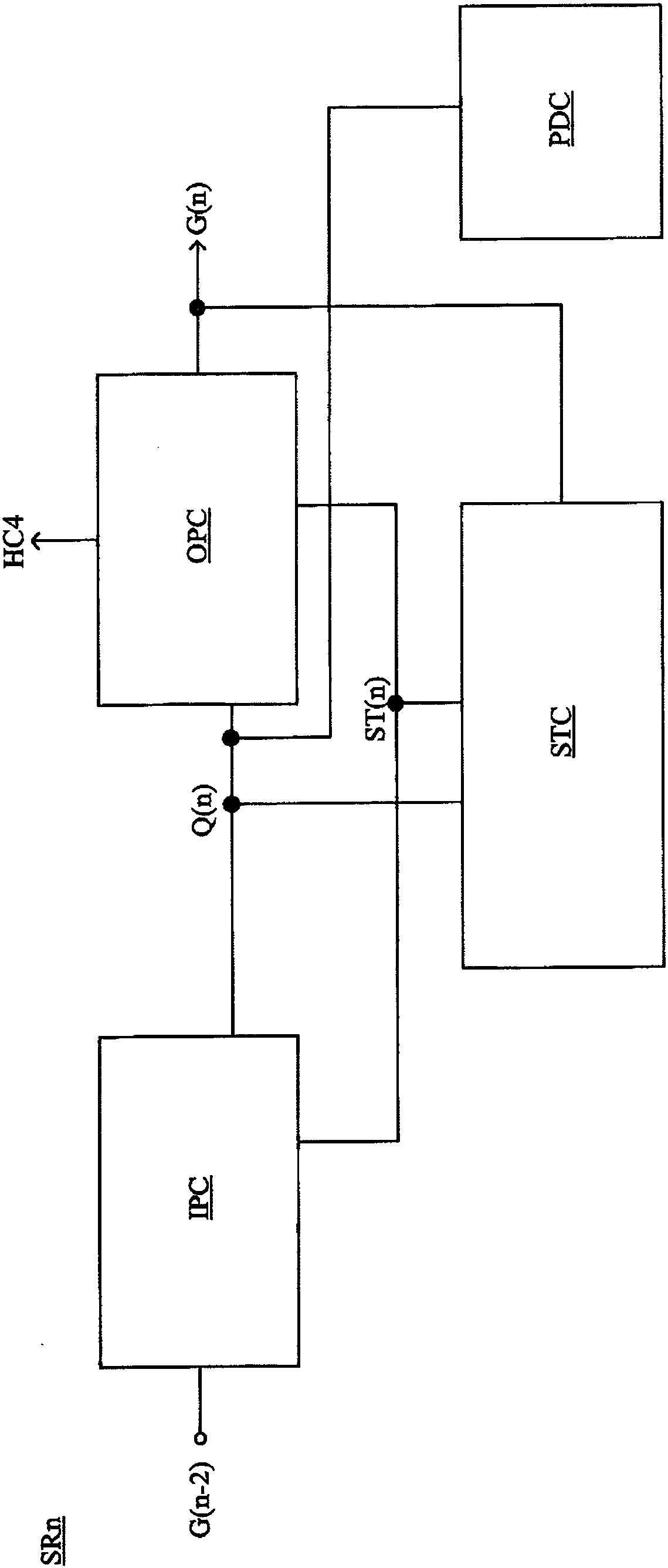
A scanning circuit comprises an output circuit, a voltage stabilization circuit, and an input circuit. The input circuit comprises: a first switch, a second switch, and a third switch. The first switch is turned on according to a first control voltage on a control node to provide a first operating voltage for a working node. The second switch is turned on according to a first control voltage on the control node to provide a first operating voltage for an operating node. The third switch is configured to provide a first control voltage for the control node. When the first switch is turned on, the first control voltage on the control node changes according to a voltage change on the working node.

Description

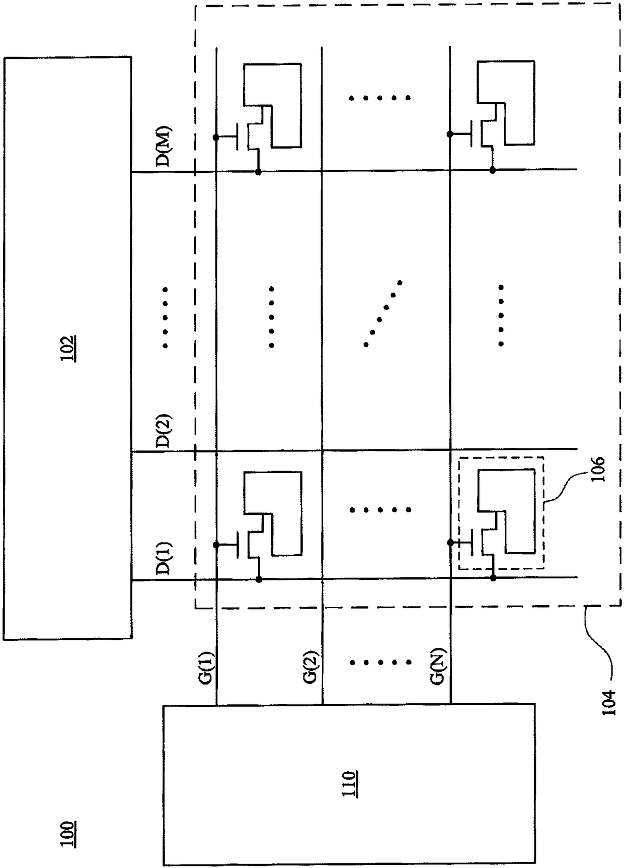
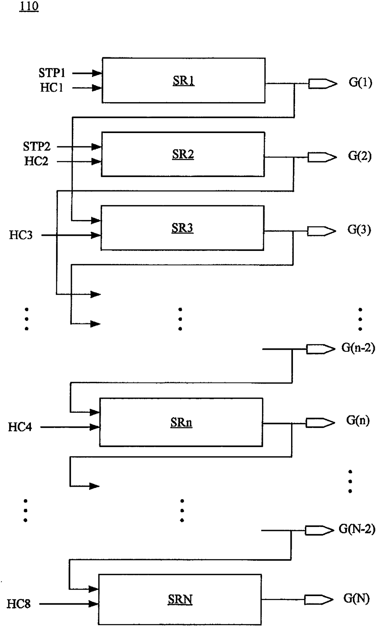
technical field [0001] The invention relates to an electronic circuit. Specifically, the present invention relates to a scanning circuit. Background technique [0002] With the development of science and technology, display devices have been widely used in people's lives. [0003] Generally speaking, a display panel may include a gate driving circuit, a source driving circuit and a plurality of pixel circuits arranged in a matrix. The gate driving circuit can generate a plurality of gate signals in sequence, and provide these gate signals to the pixel circuits to turn on the switches in the pixel circuits column by column. The source driving circuit can simultaneously generate a plurality of data voltages, and provide these data voltages to the pixel circuits with the switches turned on, so that the pixel circuits with the switches turned on operate according to the data voltages. In this way, the image can be updated and displayed on the display panel. [0004] In some ...

Claims


Application Information

Patent Timeline
Patent Type & Authority Applications(China)
IPC IPC(8): G09G3/20G09G3/36
CPCG09G3/20G09G3/3677
Inventor 林峻锋李明贤洪凱尉塗俊达杨创丞林逸承
Owner AU OPTRONICS CORP
Learn More