Isolated modular multi-level converter

A modular multi-level converter technology, applied in the direction of adjusting electrical variables, converting AC power input to DC power output, and converting DC power input to DC power output, etc., can solve the problem of damaged switch tubes and converters that cannot work normally and other problems, to achieve high power density, fast blocking of short-circuit fault current, and high reliability

Active Publication Date: 2018-06-12
NORTHEAST DIANLI UNIVERSITY
6 Cites 10 Cited by

AI-Extracted Technical Summary

Problems solved by technology

[0002] The isolated modular multilevel converter has the advantages of no need for high-voltage side capacitor support and voltage equalization control. However, when a short-circuit fault occurs on the high-voltage DC side, even if the active switch tubes of the subsequent stage are all turned off, the...

Abstract

The invention discloses an isolated modular multi-level converter, which comprises three phase units linked to high-voltage direct current ports (PH, NH) in parallel; every phase unit is composed of upper and lower bridge arms; outgoing lines of electric joint points (N1, N2, N3) of the upper and lower bridge arms of three phase units are high-voltage alternating current ports (a, b, c) after linking with filter inductors in series; every bridge arm is composed of a single-grade high frequency isolating type submodule with high-voltage direct current side fault current blocking ability and a bridge-arm reactor Lm; the single-grade high frequency isolating type submodule comprises a front grade part, a high-frequency transformer part and a back grade part; the back grade part can block failed current when the high-voltage direct current side has short-circuited failure, thus the failure at the direct current side is removed. The converter structure is simple, and the converter has the advantages that the isolated modular multi-level converter is free from the high-voltage-free side capacitor and voltage-sharing control, and others; the high-voltage direct current side failure voltage can be rapidly cut off.

Application Domain

Emergency protective circuit arrangementsDc-dc conversion +2

Technology Topic

ModularityCapacitance +18

Image

  • Isolated modular multi-level converter
  • Isolated modular multi-level converter
  • Isolated modular multi-level converter

Examples

  • Experimental program(1)

Example Embodiment

[0051] In order to make the objectives and advantages of the present invention clearer, the present invention will be further described in detail below in conjunction with embodiments. It should be understood that the specific embodiments described herein are only used to explain the present invention, but not to limit the present invention.
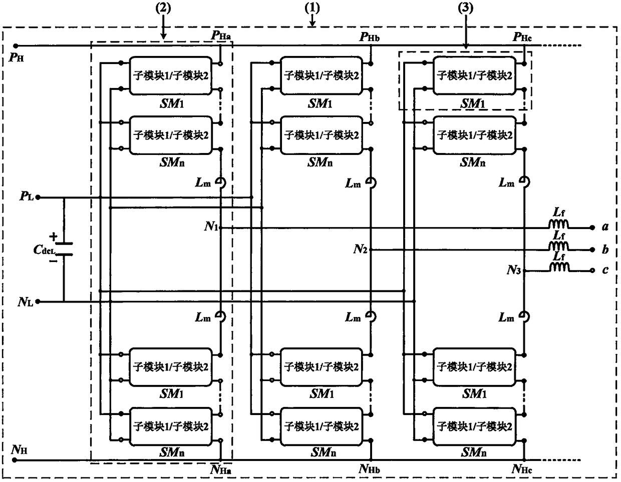
[0052] Such as figure 1 As shown, the embodiment of the present invention provides an isolated modular multi-level converter with high-voltage DC side fault current blocking capability. The converter 1 includes three high-voltage DC ports (P H , N H ) Between the phase unit 2, each phase unit 2 is composed of upper and lower bridge arms, the electrical connection points of the upper and lower bridge arms of the three phase units (N 1 , N 2 , N 3 ) After the lead wire is connected in series with the filter inductor, there are high-voltage AC ports (a, b, c). Each bridge arm consists of n single-stage high-frequency isolation sub-modules 3 with high-voltage DC side fault current blocking capability and a bridge arm Reactor L m Composition; the positive extreme of the upper bridge arm of the three phase units 2 (P Ha , P Hb , P Hc ) Is connected to the positive pole P of the high voltage DC port of the converter H , The negative end of the lower bridge arm of the three-phase unit 2 (N Ha , N Hb , N Hc ) Is connected as the negative N of the high-voltage DC port of the converter H;
[0053] Each single-stage high-frequency isolation sub-module 3 of the present invention with a high-voltage DC side fault current blocking capability includes a front-stage part 4, a high-frequency transformer part 5, and a back-stage part 6, and according to the fault current in the back-stage part The connection position of the blocking switch module 8 is different, and it can be divided into two sub-modules: the first sub-module and the second sub-module. Its topology is as follows: figure 2 , 3 As shown, the high-frequency AC side of the front-end part is connected to the primary side of the high-frequency transformer T, and the high-frequency AC side of the back-end part is connected to the secondary side of the high-frequency transformer T. The front-end ports of all sub-modules are connected in parallel to form a common low voltage DC side port (P L , N L ), the rear-stage ports are connected in series to form a high-voltage DC port (P H , N H ), the positive end of the bridge arm of the three phase units (P Ha , P Hb , P Hc ) Is connected to the positive pole P of the high voltage DC port of the converter H , Similarly, the negative end of the lower bridge arm of the three-phase unit (N Ha , N Hb , N Hc ) Is connected as the negative N of the high-voltage DC port of the converter H.
[0054] The front stage part contains 4 active switching tubes (such as IGBT) with anti-parallel diodes Q 1 -Q 4 H bridge and low-voltage side DC capacitor C dcL , The latter part contains 6 active switching tubes with anti-parallel diodes (such as IGBT) Q 5 ~Q 10 (The first submodule) or contains 6 active switch tubes with anti-parallel diodes (such as IGBT) Q 11 ~Q 16 (Second sub-module) and voltage clamping circuit, the active transistor Q with anti-parallel diode 1 ~Q 16 The collectors are respectively connected to the cathodes of the respective freewheeling diodes, and the emitters are respectively connected to the anodes of the respective freewheeling diodes.
[0055] Q in the previous part 1 With Q 3 Connected in series with the low-voltage side DC capacitor C dcL In parallel, the Q 1 Emitter and Q 3 The collector is connected and used as the primary end of the high-frequency transformer E, Q 2 Emitter and Q 4 The collector is connected and used as the other end of the primary side of the high-frequency transformer F, Q 1 The collector and C dcL Is connected to the positive pole, Q 3 Emitter and C dcL The negative pole is connected; the Q 2 With Q 4 Connected in series with the low-voltage side DC capacitor C dcL Parallel, Q 2 The collector and C dcL The positive pole of Q 4 Emitter and C dcL The negative pole is connected; the Q 1 , Q 2 The collector of C dcL The positive terminal of the sub-module is connected to the positive terminal A, Q 3 , Q 4 Emitter and C dcL Connect to the negative terminal of the sub-module and serve as the negative terminal B of the front stage of the sub-module.
[0056] Such as figure 2 As shown, the rear-stage part of the first sub-module includes a fifth active switch Q 5 , A sixth active switch Q 6 , A seventh active switch Q 7 , An eighth active switch Q 8 , A ninth active switch tube Q 9 , A tenth active switch Q 10 , The collector of each active switching tube is connected to the cathode of the respective free-wheeling diode, and the emitter is connected to the anode of the respective free-wheeling diode; the fault current blocking switch module consists of the ninth active switching tube Q 9 And the tenth active switch Q 10 Composition, the ninth active switch tube Q 9 The emitter and the seventh active switch Q 7 Is connected to the emitter, the tenth active switch Q 10 The emitter and the eighth active tube Q 8 The emitter is connected; the fifth active switch Q 5 The emitter and the seventh active switch Q 7 The collector of the high-frequency transformer is connected and used as the secondary terminal G of the high-frequency transformer, and the sixth active switch tube Q 6 The emitter and the eighth active switch Q 8 The collector is connected to the other end H of the secondary side of the high-frequency transformer; the fifth active switch tube Q 5 And the sixth active switch Q 6 The collector of the sub-module is connected and used as the positive electrode C of the rear stage of the sub-module, and the ninth active switch tube Q 9 With the tenth active switch Q 10 Is connected to the collector and serves as the negative electrode D of the rear stage of the sub-module;
[0057] Such as image 3 As shown, the latter part of the second sub-module contains an eleventh active switch tube Q 11 , A twelfth active switch Q 12 , A thirteenth active switch Q 13 , A fourteenth active switch Q 14 , A fifteenth active switch Q 15 , A sixteenth active switch Q 16 , The collector of each active switch tube is connected to the cathode of the respective freewheeling diode, and the emitter is connected to the anode of the respective freewheeling diode; the fault current blocking switch module is set by the fifteenth active switch tube Q 15 And the sixteenth active switch Q 16 Composition, the eleventh active switch tube Q 13 The collector and the fifteenth active switch Q 15 Connected to the collector, the twelfth active switch tube Q 12 The collector and the sixteenth active tube Q 16 The collector is connected; the eleventh active switch tube Q 11 The emitter and the 13th active switch Q 13 The collector is connected and used as the secondary terminal G of the high-frequency transformer, the twelfth active switch tube Q 12 The emitter and the fourteenth active switch Q 14 The collector is connected to the other end H of the secondary side of the high-frequency transformer; the fifteenth active switch tube Q 15 With the sixteenth active switch Q 16 The emitter is connected to the positive pole C of the rear stage of the sub-module, and the eleventh active switch tube Q 11 With the twelfth active switch tube Q 12 The collector electrode is connected and used as the negative electrode D of the rear stage of the sub-module.
[0058] The voltage clamping circuit 7 in the latter part includes a capacitor C 1 , Resistance R 1 , 4 diodes D 1 ~D 4 , The D 1 With D 3 After series connection with C 1 , R 1 Parallel, the D 2 With D 4 After series connection with C 1 , R 1 Parallel, D 1 , D 2 The cathode and C 1 , R 1 Connect to the positive pole, D 2 , D 4 The anode and C 1 , R 1 Connect the negative pole of D 1 The anode and D 3 The cathode of the high-frequency transformer is connected to the secondary terminal G, D 2 The anode and D 4 The cathode of the high-frequency transformer is connected to the H-phase at the other end of the secondary side.
[0059] During normal operation, the fault current blocking the 2 active switch tubes (Q 9 , Q 10 Or Q 15 , Q 16 ) Is always in the open state and does not affect the normal operation of the circuit. When a short-circuit fault occurs on the high-voltage DC side, the H-bridge active switch tube (Q 5 , Q 6 , Q 7 , Q 8 Or Q 11 , Q 12 , Q 13 , Q 14 ) At the same time quickly to the fault current blocking switch module's 2 active switching tubes (Q 9 , Q 10 Or Q 15 , Q 16 ) Shut-off signal, due to the reversed fault current blocking switch module, the subsequent part of the H-bridge active switch tube (Q 5 , Q 6 , Q 7 , Q 8 Or Q 11 , Q 12 , Q 13 , Q 14 ) The energy feed circuit between the AC side and the fault point formed by anti-parallel diodes can block the short-circuit fault current on the high-voltage DC side, thereby achieving fault isolation on the DC side.
[0060] The above are only the preferred embodiments of the present invention. It should be pointed out that for those of ordinary skill in the art, without departing from the principle of the present invention, several improvements and modifications can be made, and these improvements and modifications should also be made. It is regarded as the protection scope of the present invention.

PUM

no PUM

Description & Claims & Application Information

We can also present the details of the Description, Claims and Application information to help users get a comprehensive understanding of the technical details of the patent, such as background art, summary of invention, brief description of drawings, description of embodiments, and other original content. On the other hand, users can also determine the specific scope of protection of the technology through the list of claims; as well as understand the changes in the life cycle of the technology with the presentation of the patent timeline. Login to view more.

Similar technology patents

Frame shaping device

InactiveCN109834137AImproved calibration accuracy and consistencymove quickly
Owner:常州豪爵铃木摩托车有限公司

Synthetic protector for intelligent motor

InactiveCN101478141Amove quickly
Owner:SHENGLI OIL FIELD HIGHLAND GASOLINEEUM EQUIP

Combined type screw nut

InactiveCN104728246Amove quicklyquick lock
Owner:HOHAI UNIV CHANGZHOU

Hot-pressing sealing machine

PendingCN113060363Amove quicklyReliable control
Owner:重庆市万州职业教育中心

Hoisting type product tray of combined color sorting mechanical arm

InactiveCN104226616Amove quicklyImprove efficiency
Owner:SUZHOU CHANG FEI AUTOMATION EQUIP FACTORY

Classification and recommendation of technical efficacy words

  • move quickly

Novel mechanical arm based on double-bevel deflection joints

InactiveCN104608146AImprove power densitymove quickly
Owner:UNIV OF SCI & TECH OF CHINA

Withstand voltage test mechanism

InactiveCN103760477Amove quicklyImprove efficiency
Owner:AD TOYO LIGHTING GUANGZHOU

Novel rapid mechanical-type high-voltage direct current breaker

InactiveCN107565524Aavoid breaking failuremove quickly
Owner:CHINA SOUTH POWER GRID ELECTRIC POWER RES INST +1

Automatic shielding test device and test flow line thereof

ActiveCN105334360Asimple controlmove quickly
Owner:SHENZHEN JIACHEN TECH

Chinese zither pick grove

InactiveCN102613738Amove quicklyshorten the time
Owner:SICHUAN UNIV
Why Eureka
Try Eureka