[0022] The technical solutions in the embodiments of the present invention will be clearly and completely described below in conjunction with the accompanying drawings in the embodiments of the present invention. Obviously, the described embodiments are only a part of the embodiments of the present invention, rather than all the embodiments. Based on the embodiments of the present invention, all other embodiments obtained by those of ordinary skill in the art without creative work shall fall within the protection scope of the present invention.
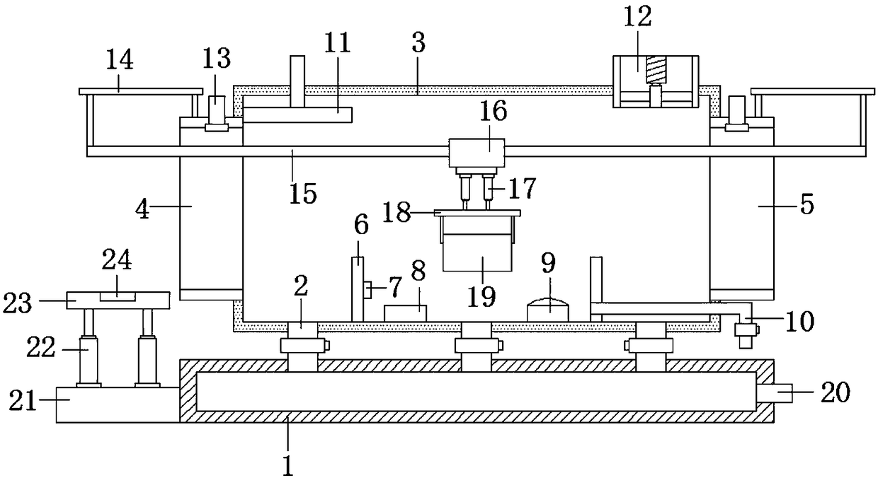
[0023] See Figure 1-2 As shown, this embodiment is a vegetable cleaning device for vegetable sales and production. It includes a base 1, a sewage pipe 2 is provided on the top of the base 1, a cleaning box 3 is provided on the top of the sewage pipe 2, and the left side of the cleaning box 3 A feed port 4 is provided, a discharge port 5 is provided on the right side of the cleaning box 3, partitions 6 are symmetrically provided at the left and right sides of the inner cavity bottom of the cleaning box 3, and a liquid level sensor is provided on the right side of the left partition 6 7. The bottom of the inner cavity of the cleaning box 3 is provided with a bubble generating device 8 and an electronic active oxygen device 9, and the bubble generating device 8 is located on the left side of the electronic active oxygen device 9, and the bubble generating device 8 and the electronic active oxygen device 9 are located in two groups Between the partitions 6, a water inlet pipe 10 is provided on the right side of the right partition 6, and the end of the water inlet pipe 10 away from the partition 6 extends out of the cleaning box 3; the top left side of the inner cavity of the cleaning box 3 is provided with a sprayer 11, and the top water inlet end of the sprinkler 11 extends out of the top of the cleaning box 3, the top right side of the cleaning box 3 is provided with a blower 12, and the tops of the inlet 4 and the top of the discharge opening 5 are close to the side of the cleaning box 3. All are equipped with air curtains 13, and the tops of the inlet 4 and the discharge outlet 5 are provided with a sliding rod bracket 14 on the side away from the cleaning box 3, and a sliding rod 15 is arranged between the two groups of sliding rod brackets 14 and sliding The rod 15 penetrates the cleaning box 3, the sliding rod 15 is sleeved with an electric sliding sleeve 16, and the bottom of the electric sliding sleeve 16 is provided with an electronically controlled pneumatic telescopic rod 17, and the bottom of the electronically controlled pneumatic telescopic rod 17 is provided with a hanger 18, the hanger A cleaning frame 19 is provided at the bottom of the base 18; a sewage outlet 20 is provided on the right side wall of the base 1, a support platform 21 is provided on the left side of the base 1, and an electronically controlled hydraulic telescopic rod 22 is provided on the top of the support platform 21. The top of the hydraulic telescopic rod 22 is provided with a lifting platform 23, and the top of the lifting platform 23 is fitted with a gravity sensor 24; the left side of the partition 6 on the left side of the inner cavity of the cleaning box 1 is the rinsing station, and the two sides of the inner cavity of the cleaning box 1 Between the group partitions 6 is a dipping station, and the right side of the partition 6 in the inner cavity of the cleaning box 3 is a draining station.
[0024] When cleaning vegetables, first put the vegetables into the cleaning frame 19 and transport them to the lifting platform 23. The gravity sensor 24 senses the weight of the cleaning frame 19 and the vegetables in it, so that the operator can adjust the weight of the vegetables. To avoid damage to the equipment due to heavy vegetables, the height of the cleaning frame 19 is raised by the electronically controlled hydraulic telescopic rod 22, so that it can be suspended to the bottom of the hanger 18, and the electric sliding sleeve 16 moves the cleaning frame 19 along The slide bar 15 moves, and when it enters the washing station, the vegetables are washed by the liquid sprayed by the sprayer 11. After the washing work is completed, it is transported to the dipping station, and it is telescopically controlled by electric pressure. The telescopic movement of the rod 17 causes the cleaning frame 19 to be settled into the cleaning tank between the two sets of partitions 6. The air bubble generating device 8 and the electronic active oxygen device 9 work, and the generated air bubbles and active oxygen can improve the cleaning of vegetables Efficiency and cleaning effect, then the cleaning frame 19 is moved to the draining station, through the blowing action of the blower 12, the airflow on the surface of the cleaning frame 19 is accelerated, which can accelerate the draining efficiency of the vegetables in the cleaning frame 19, and the air curtain 13 can Reduce the water mist generated during cleaning to float out through the feed inlet 4 and the discharge outlet 5, causing pollution to the surrounding environment. The sewage generated during the cleaning process is discharged to the inner cavity of the base 1 through the sewage pipe 2 and then from the sewage outlet 20 discharge.
[0025] The spray angle of the sprinkler 11 is forty-five degrees, so that the sprinkler 11 can better spray clean water on the cleaning frame 19. The sewage pipe 2 has three groups of the same structure, and the three groups of sewage pipes 2 are connected with each other. The leaching station, the dipping station and the draining station correspond to each other, so that the sewage discharge of the three stations can be better adjusted and controlled. The maximum load of the cleaning frame 19 is 200 kg, and the front and back sides of the cleaning frame 19 The top of the wall is provided with a hanging buckle 191, the inner cavity of the cleaning frame 19 is provided with a winding shaft 192, and the left and right ends of the winding shaft 192 respectively penetrate the left and right side walls of the cleaning frame 19, and the left and right side walls of the cleaning frame 19 are provided with sliding Groove 193, an unfolding shaft 194 is arranged between the two sets of sliding grooves 193, an anti-floating net 195 is wound on the outer wall of the reeling shaft 192, and the unfolding end of the anti-floating net 195 is connected with the unfolding shaft 194, and the left end of the unfolding shaft 194 is provided There is a connecting plate 196. Both the top of the connecting plate 196 and the top front side of the cleaning frame 19 are provided with threaded holes 197. The length of the anti-floating net 195 is the same as the length of the inner cavity of the cleaning frame 19. The vegetables are placed in the cleaning frame 19 After being in the cavity, the unfolding shaft 194 moves along the sliding groove 193, so that the anti-floating net 195 is unfolded, and the unfolding shaft 194 is fixed by the joint action of the bolt and the connecting plate 196, and the anti-floating net 195 can make the cleaning frame 19 Vegetables in the dipping process are not easy to float.
[0026] A specific application of this embodiment is: the vegetable cleaning device for vegetable sales and production provided by the present invention has a reasonable structure design. Vegetables are subjected to three steps of rinsing, dipping, and draining through the action of the electric sliding sleeve 16 and the hanger 18. Steps reduce the manual dredging process and the labor intensity of the operator. The cleaning effect can be improved by first rinsing and then dipping, and the anti-floating net 195 can prevent vegetables from floating during dipping. , And then achieve a better cleaning effect.
[0027] In the description of this specification, the description with reference to the terms "one embodiment", "example", "specific example", etc. means that the specific feature, structure, material or characteristic described in combination with the embodiment or example is included in at least the present invention. In one embodiment or example. In this specification, the schematic representations of the above terms do not necessarily refer to the same embodiment or example. Moreover, the described specific features, structures, materials or characteristics may be combined in any one or more embodiments or examples in a suitable manner.
[0028] The preferred embodiments of the present invention disclosed above are only used to help explain the present invention. The preferred embodiment does not describe all the details in detail, nor does it limit the invention to only the described specific embodiments. Obviously, many modifications and changes can be made according to the content of this manual. This specification selects and specifically describes these embodiments in order to better explain the principles and practical applications of the present invention, so that those skilled in the art can understand and use the present invention well. The present invention is only limited by the claims and their full scope and equivalents.