Pleural fluid collecting and sampling all-in-one drainage bottle

A drainage bottle, an integrated technology, applied in the field of medical equipment, can solve the problems of the patient's pleural fluid impact, cumbersome, lung infection, etc., and achieve the effect of isolating air

Active Publication Date: 2018-06-15
SHANGHAI PULMONARY HOSPITAL
View PDF3 Cites 0 Cited by
  • Summary
  • Abstract
  • Description
  • Claims
  • Application Information

AI Technical Summary

Problems solved by technology

[0002] Existing drainage of hemothorax, pneumothorax, empyema and patients after thoracotomy generally need to be equipped with a chest drainage bottle. During the process of using the chest drainage bottle, medical staff need to detect its physiological parameters; the existing chest cavity For fluid collection, the drainage bottle needs to be removed before sample delivery, so the pleural fluid drainage bottle needs to be replaced. This operation requires multiple chest drainage bottles, and it is troublesome to replace
Moreover, most of the existing chest drainage bottles are in a negative pressure state, which is difficult to take off when the patient uses them.
Moreover, when the existing chest drainage bottle is replaced, it is necessary to affect the normal extraction of the patient's pleural fluid, because the patient will inhale air when changing, and if the operation is not performed, it is easy to cause lung infection
And when the patient needs to configure the chest drainage bottle for a long time, it is necessary to detect the pleural effusion from time to time and replace the chest drainage bottle, and after the accumulation of the pleural effusion, only the replacement is required, which is very cumbersome

Method used


Image

  • Pleural fluid collecting and sampling all-in-one drainage bottle
  • Pleural fluid collecting and sampling all-in-one drainage bottle
  • Pleural fluid collecting and sampling all-in-one drainage bottle

Examples


Embodiment Construction

[0031] The technical solution of the present invention will be further described in detail below in conjunction with the accompanying drawings.

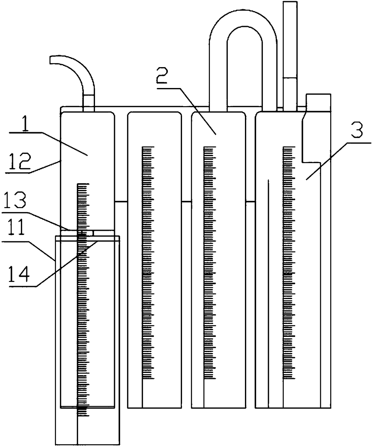
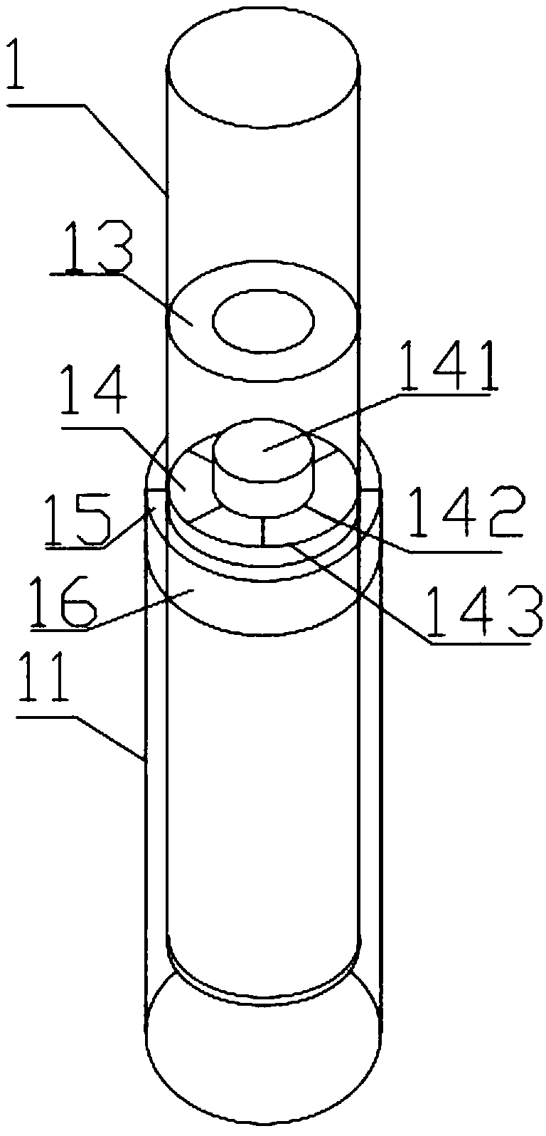
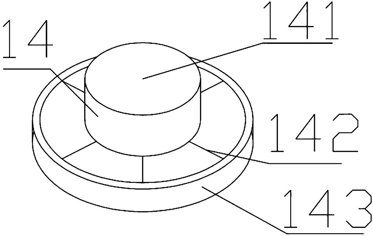
[0032] figure 1 It is a schematic structural view of a pleural fluid collection and sampling integrated drainage bottle in a preferred embodiment of the present invention; figure 2 It is a schematic diagram of the structure of the effusion cavity in a preferred embodiment of the present invention; image 3 It is a schematic structural diagram of a displacement plate in a preferred embodiment of the present invention; Figure 4 It is a schematic diagram of the structure of the effusion cavity in a preferred embodiment of the present invention; Figure 5 It is a schematic diagram of the structure of the liquid accumulation cavity in a preferred embodiment of the present invention.

[0033] It should be noted that, in the case of no conflict, the embodiments of the present invention and the features in the embodiments can be combine...


PUM


Abstract

The invention provides a pleural fluid collecting and sampling all-in-one drainage bottle. The bottle comprises a hydrops cavity, a water seal cavity and a pressure regulating cavity, the hydrops cavity comprises a cylindrical outer sleeve, an inner hydrops cavity, an annular ring, a shift tray, an outer sleeve top cover ring and an outer sleeve annular magnetic ring; the inner hydrops cavity is shaped like a cylinder, and a bottom opening is formed in the bottom of the inner hydrops cavity; the annular ring is horizontally and fixedly arranged in the hydrops cavity, and an annular ring hole is formed in the center of the circle of the annular ring; the shift tray is horizontally arranged in the inner hydrops cavity, and the shift tray is provided with a shift tray hole plug matched with the annular ring hole, a connecting rod radially connected with the shift tray hole plug and a shift tray annular magnetic outer ring connected with the connecting rod. Accordingly, sampling and sampledelivery can be performed very easily, use of the pleural fluid drainage bottle is not affected, negative pressure in the bottle can be controlled, by means of relative sliding and control of a magnetic ring, the pleural fluid drainage bottle can be opened and locked conveniently at any time, and simpleness and convenience are achieved.

Description

technical field [0001] The invention relates to the field of medical equipment, in particular to an integrated drainage bottle for collecting and sampling pleural fluid. Background technique [0002] Existing drainage of hemothorax, pneumothorax, empyema and patients after thoracotomy generally need to be equipped with a chest drainage bottle. During the process of using the chest drainage bottle, medical staff need to detect its physiological parameters; the existing chest cavity The collection of fluid needs to remove the drainage bottle first and then send the sample, so the pleural fluid drainage bottle needs to be replaced, which requires multiple thoracic drainage bottles during this operation, and it is troublesome to replace. Moreover, most of the existing thoracic drainage bottles are in a negative pressure state, which is difficult to take off when the patient uses them. And the existing chest cavity drainage bottle necessarily needs to affect the patient's pleura...

Claims


Application Information

Patent Timeline
Patent Type & Authority Applications(China)
IPC IPC(8): A61M1/00A61B10/00
CPCA61M1/0001A61B10/0045A61M2210/101A61M2210/005
Inventor 刘莉王季颖黄李华
Owner SHANGHAI PULMONARY HOSPITAL
Why Eureka
Try Eureka