
Potentiometer assembling machine with automatic retainer ring mounting function

A potentiometer and assembly machine technology, applied in assembly machines, metal processing equipment, manufacturing tools, etc., can solve the problems of low assembly efficiency, low installation quality, and pushing the collar into the card slot, so as to improve production efficiency and quality, Improve efficiency and quality, improve the effect of quality

Active Publication Date: 2018-06-15
广东钺河智能科技有限公司
View PDF5 Cites 10 Cited by
  • Summary
  • Abstract
  • Description
  • Claims
  • Application Information

AI Technical Summary

Problems solved by technology

[0002] The potentiometer is composed of shaft core E, shaft sleeve D, collar C, stopper seat B, shrapnel A, fluctuation plate, brush, and base with coded hardware. Among them, the shaft core E, shaft sleeve D, and collar need to be C. The stopper seat B and shrapnel A are assembled into semi-finished products (such as figure 2 shown), where the shaft sleeve needs to be placed on the shaft core first, and then the shaft core is limited in the shaft sleeve by the collar, and then the stopper seat is placed in the shaft sleeve and set on the shaft core for riveting and fixing with the shaft core The difficulty in the assembly of traditional potentiometers lies in the installation of the collar. After the collar is placed on the shaft core, the collar must be pushed into the slot in the middle of the shaft core. The traditional assembly machine can only put the collar on the shaft core. , and the collar cannot be pushed into the card slot correctly, the installation quality is low, the assembly efficiency is low, the product quality is unstable, and the product qualification rate is low, etc.

Method used


Image

  • Potentiometer assembling machine with automatic retainer ring mounting function
  • Potentiometer assembling machine with automatic retainer ring mounting function
  • Potentiometer assembling machine with automatic retainer ring mounting function

Examples


Embodiment Construction

[0033] Refer to attached figure 1 To attach Figure 10 The specific embodiment of the present invention is introduced.

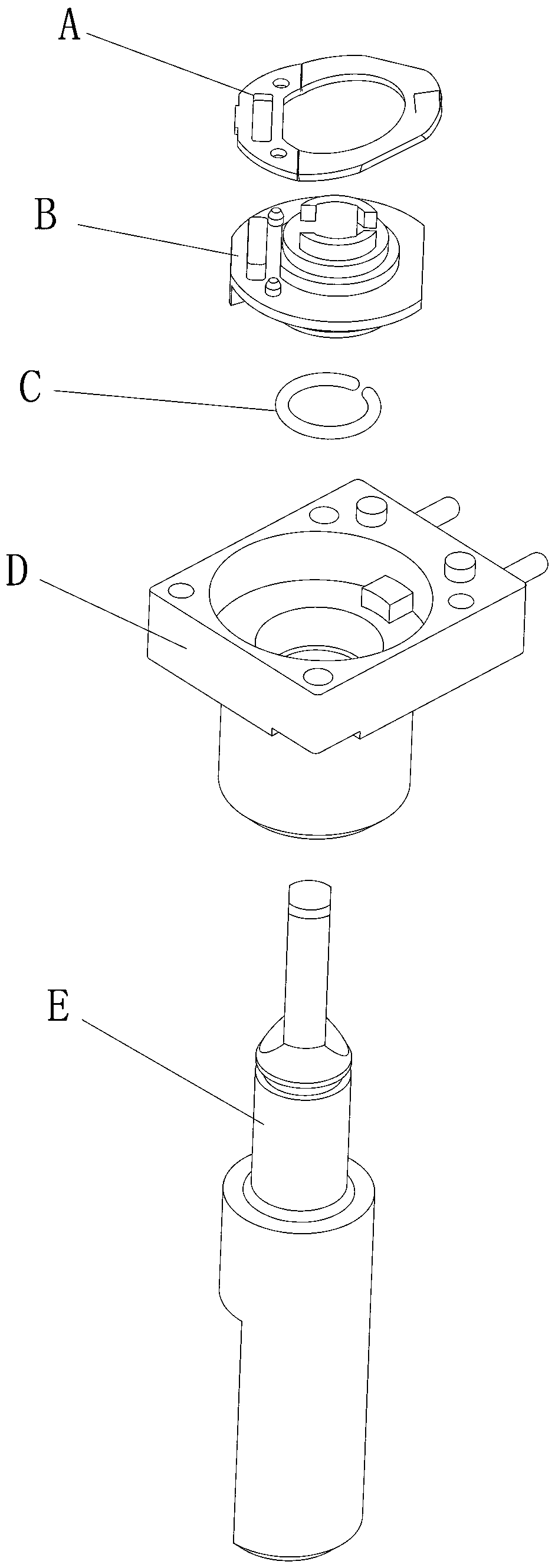
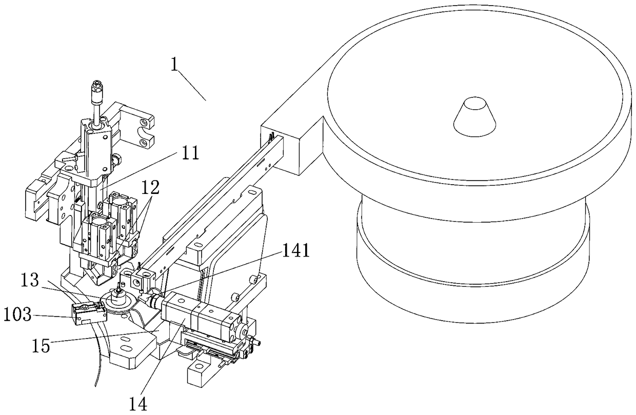
[0034] Such as Figure 1-10 As shown in the figure, a potentiometer assembly machine for automatically installing collars includes an assembly table 10 with a turntable 101 that rotates at intervals in the center. A plurality of jigs 103 are arranged on the turntable 101 at equal angles, and the turntable 101 is arranged sequentially according to the direction of rotation. Shaft core feeding device 1, shaft sleeve feeding device 2, collar feeding device 3, shaft sleeve oiling device 4, collar pressing device 5, stop seat and shrapnel feeding device 75, the stop seat and The pressure riveting device 8 and the unloading device 9 for shaft core riveting, the rear of the stop seat and the shrapnel feeding device 75 are connected with a shrapnel riveting device 7, and the shrapnel riveting device 7 is connected with a shrapnel material tape reel 102 and a stop...


PUM


Abstract

The invention discloses a potentiometer assembling machine with an automatic retainer ring mounting function. The potentiometer assembling machine comprises an assembling platform with a rotatable turntable with a gap in the center. Multiple jigs are arranged on the turntable at equal angles. A shaft core feeding device, a shaft sleeve feeding device, a retainer ring feeding device, a shaft sleeveoiling device, a retainer ring press-fit device, a stopper seat and elastic piece feeding device, a rivet pressing device for riveting stopper seats and shaft cores and a discharging device are sequentially arranged on the turntable in the rotating direction. An elastic piece riveting device is connected to the rear portion of the stopper seat and the elastic piece feeding device. The elastic piece riveting device is connected with an elastic piece material strip disc and a stopper seat feeding device. A horizontal oiling device for oiling the shaft cores is connected to the shaft core feeding device. According to the potentiometer assembling machine, the elastic pieces are riveted to the stopper seats through the elastic piece riveting device and then are assembled to the shaft cores through the stopper seat and the elastic piece feeding device, and the assembling efficiency and quality are improved; and the retainer rings and the shaft cores are clamped in place through the retainerring press-fit device, and the quality of products is further improved.

Description

technical field [0001] The invention relates to the field of automatic assembling machinery, in particular to a potentiometer assembling machine for automatically installing collars. Background technique [0002] The potentiometer is composed of shaft core E, shaft sleeve D, collar C, stopper seat B, shrapnel A, fluctuation plate, brush, and base with coded hardware. Among them, the shaft core E, shaft sleeve D, and collar need to be C. The stopper seat B and shrapnel A are assembled into semi-finished products (such as figure 2 shown), where the shaft sleeve needs to be placed on the shaft core first, and then the shaft core is limited in the shaft sleeve by the collar, and then the stopper seat is placed in the shaft sleeve and set on the shaft core for riveting and fixing with the shaft core The difficulty in the assembly of traditional potentiometers lies in the installation of the collar. After the collar is placed on the shaft core, the collar must be pushed into the ...

Claims


Application Information

Patent Timeline
Patent Type & Authority Applications(China)
IPC IPC(8): B23P21/00
CPCB23P21/006Y02P70/10
Inventor 曾河
Owner 广东钺河智能科技有限公司
Features
  • Generate Ideas
  • Intellectual Property
  • Life Sciences
  • Materials
  • Tech Scout
  • Unparalleled Data Quality
  • Higher Quality Content
  • 60% Fewer Hallucinations
Learn More