High-efficiency edge grinding device for ceramic production

A high-efficiency, ceramic technology, applied in the direction of grinding drive device, grinding/polishing safety device, machine tool suitable for grinding the edge of workpiece, etc., can solve the problem that ceramic products cannot be fully polished, and the grinding device does not have dust collection The device and the surrounding area of ​​the molded product are not very regular, etc., so as to protect the health of the body, the structure is simple, and the effect of improving the grinding quality

Inactive Publication Date: 2018-06-15
蔡惠文
View PDF8 Cites 9 Cited by
  • Summary
  • Abstract
  • Description
  • Claims
  • Application Information

AI Technical Summary

Problems solved by technology

[0003] The ceramic edging device is an indispensable main equipment in the process of ceramic manufacturing. It is usually used to grind the outer surface of the fired ceramic products in order to achieve a smooth and beautiful effect. However, the existing ordinary ceramics are pressed After firing, because the periphery of the molded product is not regular, it will cause certain difficulty in grinding. The structure of the traditional polishing machine is single. Generally, the edging component is used to grind the rotating ceramic workpiece. However, due to the edging component and the ceramic workpiece The grinding surface is limited, only through the circumferential rotation of the ceramic workpiece, so that the ceramic product cannot be fully polished, and the existing grinding device does not have a dust collection device, which will bring certain hazards to the health of the operator, so there is an urgent need for a Grinding components can be flexibly adjusted and dust collection ceramic edging device to solve this problem

Method used


Image

  • High-efficiency edge grinding device for ceramic production
  • High-efficiency edge grinding device for ceramic production
  • High-efficiency edge grinding device for ceramic production

Examples


Embodiment Construction

[0023] The technical solution of this patent will be further described in detail below in conjunction with specific embodiments.

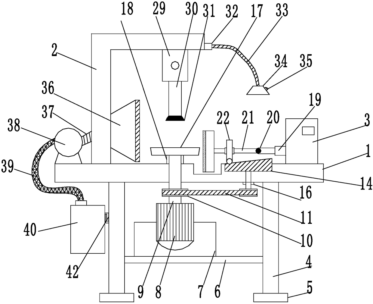
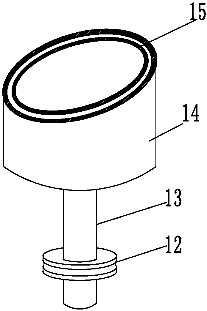
[0024] see Figure 1-5 , a high-efficiency edging device for ceramic production, including a workbench 1, a support rod 2 and a power box 3; the bottom end of the workbench 1 is connected with a support leg 4; the bottom end of the support leg 4 is provided with a pad 5, in order to ensure the stability of the workbench 1; a support plate 6 is provided between the support legs 4; a support frame 7 is provided on the support plate 6; a rotary motor 8 is supported on the support frame 7; the rotary motor 8 is connected with a main shaft 9; the main shaft 9 is provided with a driving wheel 10; the driving wheel 10 is connected to the driven wheel 12 through a belt pulley 11, so that the kinetic energy of the rotating motor 8 is output; the driven wheel 12 is set On the rotating shaft 13; the rotating shaft 13 is fixed on the workbench 1 through the b...


PUM


Abstract

The invention provides a high-efficiency edge grinding device for ceramic production. The high-efficiency edge grinding device comprises a workbench, a supporting rod and a power box; the bottom end of the workbench is connected with supporting legs; a supporting plate is arranged between the supporting legs, supporting frames are arranged on the supporting plate; a rotating motor is supported onthe supporting frames; a main shaft is connected to the rotating motor, and a driving wheel is arranged on the main shaft; the driving wheel is in transmission connection with a driven wheel through abelt wheel, and the driven wheel is arranged on a rotating shaft; a rotating cylinder is fixedly connected to the top end of the rotating shaft, and a sliding groove is formed in the rotating cylinder; a rolling ball is arranged in the sliding groove in a sliding mode; the rolling ball is fixedly arranged on a rolling wheel, and the rolling wheel is connected to a connecting rod in a sliding mode; the top end of the main shaft is connected with a rotating disc, a dust hood is arranged on the left side of the rotating disc; and a supporting rod is fixed on the left side of the upper end of theworkbench. The high-efficiency edge grinding device for ceramic production is simple in structure and convenient to use; a floating grinding disc is capable of fully grinding irregular ceramic products.

Description

technical field [0001] The invention relates to the technical field of ceramic processing, in particular to a high-efficiency edging device for ceramic production. Background technique [0002] Ceramics are various products made of clay and various natural minerals through pulverization, mixing, molding and calcination as the main raw materials. People make a kind of pottery clay and fire it at a high temperature in a special kiln called ceramics, which is the general term for pottery and porcelain. The traditional concept of ceramics refers to all artificial industrial products that use inorganic non-metallic minerals such as clay as raw materials. It includes various products made from clay or a mixture containing clay through mixing, shaping and calcination. It ranges from the roughest earthenware to the finest fine pottery and porcelain. Its main raw material is silicate minerals obtained from nature, so it belongs to the category of "silicate industry" together with ...

Claims


Application Information

Patent Timeline
Patent Type & Authority Applications(China)
IPC IPC(8): B24B9/06B24B41/06B24B47/12B24B47/20B24B55/06
CPCB24B9/06B24B41/06B24B47/12B24B47/20B24B55/06
Inventor 蔡惠文
Owner 蔡惠文
Why Eureka
Try Eureka