Deburring device for stamped chain baffle blade

A deburring and chain technology, applied in grinding/polishing safety devices, metal processing equipment, abrasive belt grinders, etc., can solve problems such as time-consuming and labor-intensive consumption, large consumption of water and abrasives, waste sewage discharge and pollution of the environment, and achieve improvement Utilization rate, man-hour saving, effect of ensuring work quality

Active Publication Date: 2018-06-15
HARBIN INST OF TECH
View PDF3 Cites 2 Cited by
  • Summary
  • Abstract
  • Description
  • Claims
  • Application Information

AI Technical Summary

Problems solved by technology

[0004] In order to solve the problem that the roller method is used for deburring existing small stamping parts, which takes time and effort, consumes a lot of water and abrasives, and pollutes the environment due to waste sewage discharge, a deburring device for stamping chain blocks is proposed.

Method used


Image

  • Deburring device for stamped chain baffle blade
  • Deburring device for stamped chain baffle blade
  • Deburring device for stamped chain baffle blade

Examples


specific Embodiment approach 1

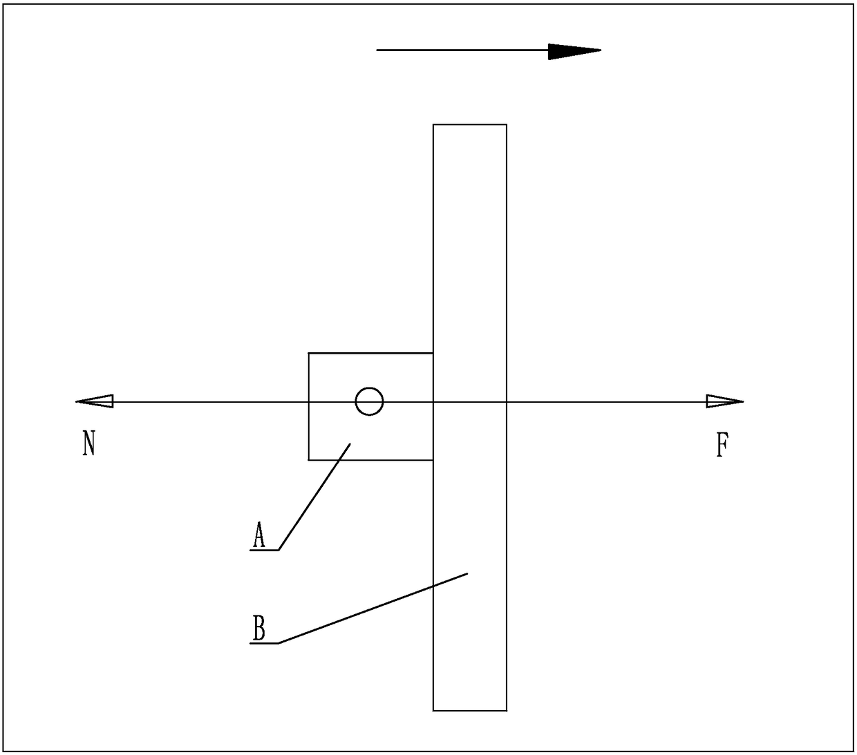
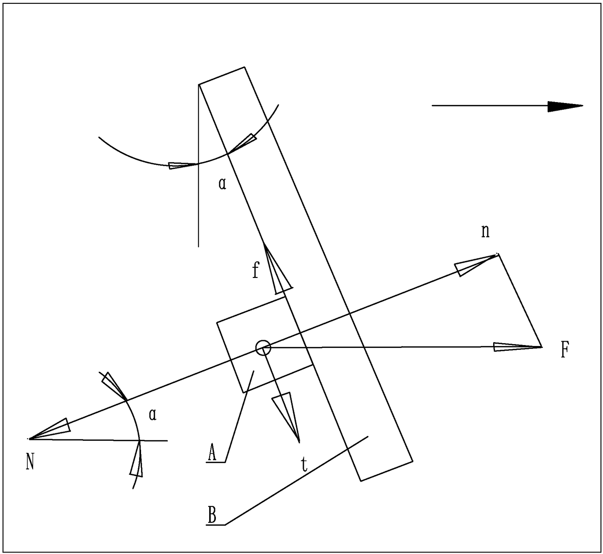
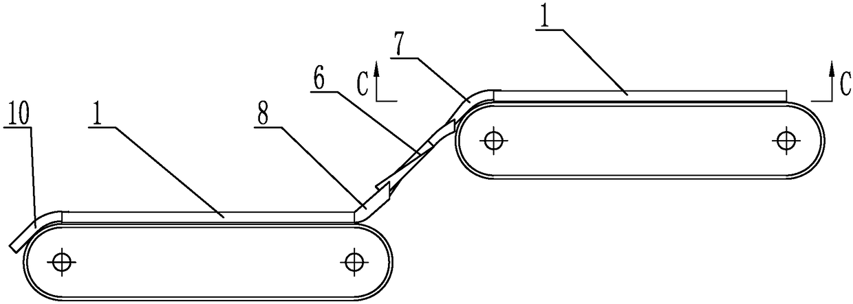
[0018] Specific implementation mode one: combine Figure 1 to Figure 9 To illustrate this embodiment, a deburring device for a stamping chain block described in this embodiment includes a reversing guide rail mechanism, two guide groove plates 1 and two abrasive belt mechanisms, and the two abrasive belt mechanisms are respectively horizontally arranged at different heights. The upper end of each abrasive belt mechanism is fixedly connected with a guide groove plate 1 respectively, and the lower end surface of the guide groove plate 1 is provided with an S-shaped material guide groove 1-1. The discharge end of the material chute 1-1 is connected, and the lower end of the reversing guide rail mechanism is connected with the feed end of the S-shaped material guide chute 1-1 on the lower abrasive belt mechanism. The abrasive belt mechanism includes an abrasive belt 3, a servo motor 4 and two The set of pulleys 2, two sets of pulleys 2 are horizontally arranged side by side, the o...

specific Embodiment approach 2

[0022] Specific implementation mode two: combination Image 6 with Figure 7 To illustrate this embodiment, the abrasive belt mechanism in this embodiment further includes a supporting plate 5 , which is horizontally arranged between two sets of pulleys 2 and supported on the inner side of the upper abrasive belt 3 . Other compositions and connection methods are the same as those in Embodiment 1.

[0023] The supporting plate 5 is designed in this way to support the upper abrasive belt 3, so as to ensure that the abrasive belt 3 carrying the parts remains horizontal, and completes the grinding of the parts.

specific Embodiment approach 3

[0024] Specific implementation mode three: combination Figure 3 to Figure 4 with Figure 6 to Figure 9 This embodiment will be described. The output shaft of the servo motor 4 in this embodiment is connected to the pulley 2 at the discharge end. Other compositions and connection methods are the same as those in the second embodiment.


PUM


Abstract

The invention discloses a deburring device for a stamped chain baffle blade, and relates to the technical field of machining. The invention aims to solve the problems of a roller method used for current deburring of small stamped parts that time and labor are consumed; a large amount of water and abrasive are consumed; and water material and sewage emission pollutes the environment. The deburringdevice comprises a reversing guide rail mechanism, two guiding groove plates and two abrasive belt mechanisms; the two abrasive belt mechanisms are separately horizontally arranged at different heights; an upper end of each abrasive belt is fixedly connected with the corresponding guiding groove plate; an S-shaped material guiding groove is formed in a lower end surface of each guiding groove plate; an upper end of the reversing guide rail mechanism is connected with a material outlet end of the S-shaped material guiding groove in the upper end abrasive belt mechanism; a lower end of the reversing guide rail mechanism is connected with a material inlet end of the S-shaped material guiding groove in the lower end abrasive belt mechanism; each abrasive belt mechanism comprises an abrasive belt, a servo motor and two groups of belt wheels which are parallelly arranged; an output shaft of each servo motor is connected with one group of the corresponding belt wheels; and every two groups ofthe belt wheels are connected through the corresponding abrasive belt. The deburring device is used for deburring machining of small stamped parts.

Description

technical field [0001] The invention relates to the technical field of mechanical processing, in particular to a deburring device for a stamped chain stopper. Background technique [0002] For the deburring of large batches of small stamping parts such as chain blocks, the roller method is now commonly used, which is characterized in that the workpiece, abrasives, and water are placed in the roller and then rolled, and the burrs are removed by the self-grinding and mutual grinding of the parts and the abrasive. It is time-consuming and labor-intensive, consumes a lot of water and abrasives, and discharges waste water to pollute the environment. Therefore, there is an urgent need and a broad market for efficient, low-cost, and pollution-free parts deburring methods. [0003] Like most of the current batch deburring methods, because it is non-targeted direct processing, the processing efficiency is doomed to be low, and at the same time, the passive processing of non-needed s...

Claims


Application Information

Patent Timeline
Patent Type & Authority Applications(China)
IPC IPC(8): B24B21/00B24B55/00
CPCB24B21/00B24B55/00
Inventor 马云辉赵喜春付佳鑫马云红吴君斌李光宝
Owner HARBIN INST OF TECH
Why Eureka
Try Eureka