Smooth polishing system

A soft, polishing head technology, applied in polishing machine tools, grinding/polishing equipment, grinding machines, etc., can solve the problems of insufficient response speed and inaccurate transmission accuracy, and achieve low device heating, fast response speed, and torque transmission efficiency. high effect

Pending Publication Date: 2018-06-15
GUANGDONG INST OF INTELLIGENT MFG
View PDF12 Cites 2 Cited by
  • Summary
  • Abstract
  • Description
  • Claims
  • Application Information

AI Technical Summary

Problems solved by technology

[0003] The shortcomings of the automatic polishing system in the prior art are that the response speed is not fast enough and the transmission accuracy is not accurate enough

Method used


Image

  • Smooth polishing system
  • Smooth polishing system
  • Smooth polishing system

Examples


Embodiment 1

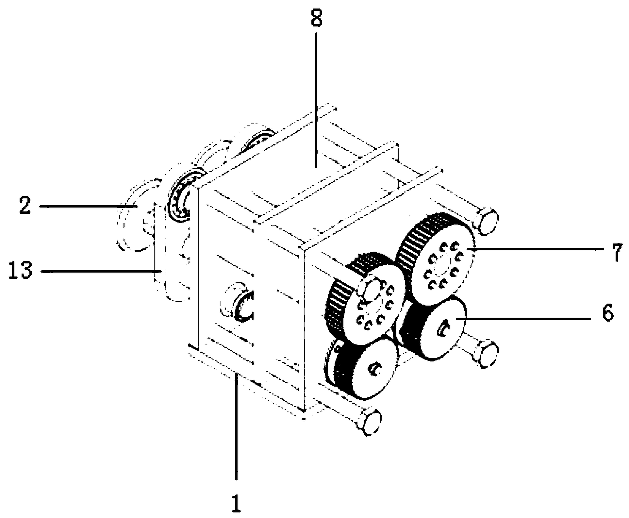
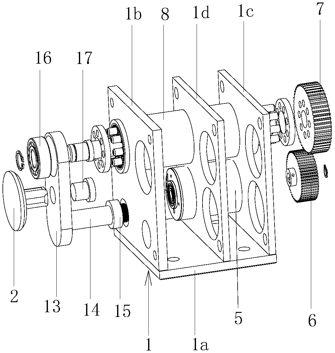
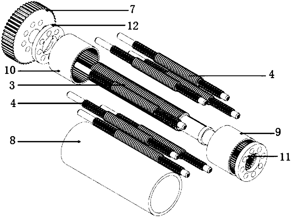
[0030] Such as Figure 1-3 As shown, the compliant polishing system includes a frame 1, a polishing head 2, a center screw 3 and several rolling screws 4, the polishing head 2 is rotatably connected to the outer end of the center screw 3 and is axially positioned on the center screw 3 Above, the center screw 3 is connected to the frame 1 by rotating around its own axis, and each rolling screw 4 rotates around its own axis and is axially positioned on the frame 1. Distributed and threadedly connected with the central screw rod 3 respectively, the polishing system also includes a drive mechanism that drives all the rolling screw rods 4 to rotate simultaneously.

[0031] Such as figure 2 As shown, in the present embodiment, the driving mechanism includes a motor 5, a driving gear 6 and a driven gear 7, the motor 5 is fixed on the frame 1, the output shaft of the motor 5 is fixedly connected with the driving gear 6, and the driving gear 6 is connected with the driven gear 7. Th...

Embodiment 2

[0046] The structure and principle of this embodiment are basically the same as those of Embodiment 1. The difference is that the drive mechanism includes a motor 5, a roller, a synchronous belt and a rotating disk. The roller is sleeved and fixed on the output shaft of the motor 5, and the synchronous belt is connected to On the rollers and the rotating disk, one end of each rolling screw 4 is fixedly connected to the rotating disk respectively, and each rolling screw 4 is evenly distributed along the circumferential direction of the rotating disk.


PUM


Abstract

The invention provides a smooth polishing system, and belongs to the technical field of polishing equipment. The technical problem that an existing polishing system is poor in response transmission precision is solved. The smooth polishing system comprises a rack, a polishing head, a center screw rod and a plurality of rolling screw rods, and the polishing head is rotationally connected to the outer end of the center screw rod and is axially positioned on the center screw rod; the center screw rod is rotationally connected to the rack around the self-axis, and all the rolling screw rods rotatearound the self-axis and are axially positioned on the rack; the rolling screw rods are distributed in the circumferential direction of the center screw rod and are in threaded transmission connection with the center screw rod. The polishing system further comprises a driving mechanism for driving all the rolling screw rods to rotate at the same time. The rolling screw rods of the polishing system are in thread line contact with the center screw rod, the contact clearance of the structure is smaller, the transmission precision is higher, the rigidity is higher, the torque which can be transmitted is larger, and movement is more stable.

Description

technical field [0001] The invention belongs to the technical field of automatic polishing equipment, and relates to a compliant polishing system. Background technique [0002] Compared with manual polishing, robot automatic polishing has the advantages of high efficiency, controllable precision and cost saving. Robotic automatic polishing is widely used in the manufacturing process of sanitary fittings, plumbing fittings, optical positioning equipment, various blades and molds. In robot automatic polishing, in order to solve the grinding problem of complex curved surface parts, reduce surface roughness and improve surface accuracy, using soft polishing tools is a very novel way. At present, commonly used polishing force control devices include pneumatic force control, electromagnetic force control, passive spring force control, etc. At present, the main way to improve efficiency is to increase the size of the polishing disc, or to increase the feed speed of the robot. ...

Claims


Application Information

Patent Timeline
Patent Type & Authority Applications(China)
IPC IPC(8): B24B27/00B24B41/00
CPCB24B27/0023B24B27/0076B24B41/007B24B39/00
Inventor 李凯格肖朝文蔡奕松曾富城周雪峰黄丹程韬波
Owner GUANGDONG INST OF INTELLIGENT MFG
Why Eureka
Try Eureka