Reverse marking device for box-type furnace production line

A production line and box-type furnace technology, applied to printing devices, measuring devices, typewriters, etc., can solve the problems of limited range of activities, large space occupation, large space, etc., to achieve convenient and flexible mechanism installation, simple and effective mechanism, and improve marking efficiency effect

Pending Publication Date: 2018-06-15
凌云吉恩斯科技有限公司
View PDF4 Cites 1 Cited by
  • Summary
  • Abstract
  • Description
  • Claims
  • Application Information

AI Technical Summary

Problems solved by technology

However, this kind of marking station has the following defects: it takes up a lot of space, and because of the narrow space of the box furnace production line, it is not conducive to the installation of the existing marking station; because of the forward marking, the marking mechanism is installed above the work table, The marking mechanism includes sliding tables, beams, longitudinal beams, support frames, etc., resulting in a complex structure above the worktable. When the end picker grabs the material for marking, the range of motion is limited, and the end picker is not easy to adjust; The space formed between the upper marking mechanisms is limited, and the working range of the blank entering the header is limited.
This kind of marking station uses the principle of leverage. When not marking, the cylinder shrinks, and the space distance between the header and the worktable increases, which increases the space for placing or taking out the material on the marking station. However, due to the marking The station adopts the principle of leverage, so the force of the header is not large, which often affects the marking effect of the m

Method used


Image

  • Reverse marking device for box-type furnace production line
  • Reverse marking device for box-type furnace production line
  • Reverse marking device for box-type furnace production line

Examples


Embodiment Construction

[0029] The principles and features of the present invention are described below in conjunction with examples, which are only used to explain the present invention and are not intended to limit the scope of the present invention.

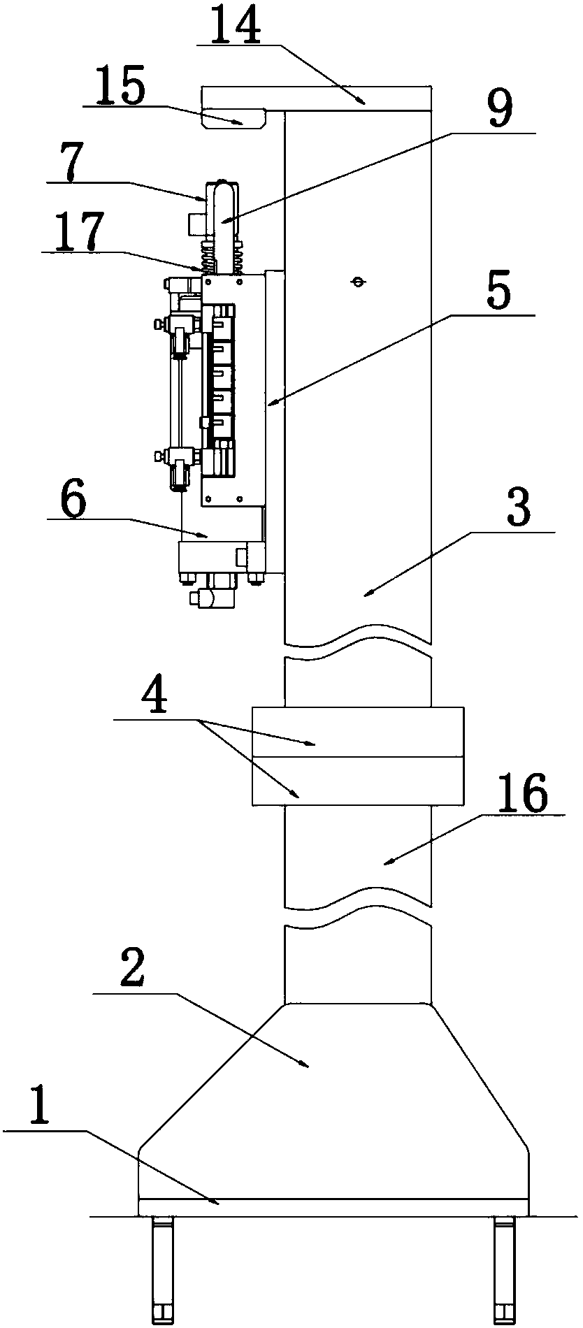
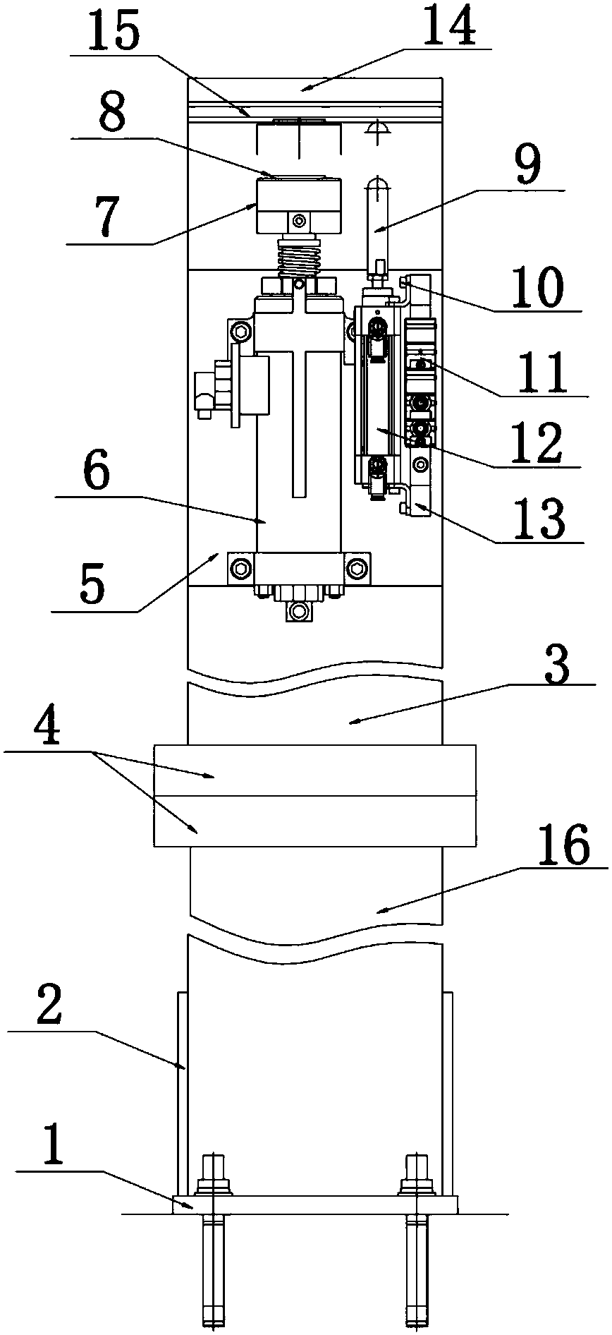
[0030] like Figure 1-Figure 4 As shown, a reverse marking device for a box furnace production line, including a column, a blank support mechanism arranged on the top of the column, a marking mechanism and a double blank detection mechanism arranged under the blank support mechanism;

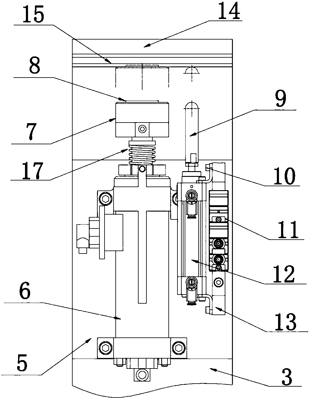
[0031] The tablet support mechanism includes a marking table fixing seat 14 and a marking cutting board 15 arranged on the lower surface of the marking table fixing seat, and the marking table fixing seat is fixedly installed on the top of the column;

[0032] The marking mechanism includes an impact cylinder, 6 marking heads 7 and a word head 8 for printing marks, the marking head is connected with the piston rod of the impact cylinder, and the word head is arranged o...


PUM


Abstract

The invention discloses a reverse marking device for a box-type furnace production line. The reverse marking device comprises a stand column, a material sheet supporting mechanism, a marking mechanismand a double material sheet detection mechanism; the material sheet supporting mechanism comprises a marking table fixing base and a marking plate, and the marking table fixing base is fixedly installed on the top of the stand column; the marking mechanism comprises an impact cylinder, a marking head and a print head used for printing marks, the marking head is connected with a piston rod of theimpact cylinder, the print head is arranged on the upper surface of the marking head, and a cylinder body of the impact cylinder is installed on the stand column through a fixing support plate; and the double material sheet detection mechanism comprises a thickness measuring head and a thickness measuring cylinder. According to the reverse marking device for the box-type furnace production line, the structure is simple, operation is convenient, the size is small, the occupied space is small, the lower surface of a material sheet can be marked without turning the material sheet, the marking efficiency of the material sheet is improved, the hot molding precision of the material sheet can not be influenced, and meanwhile the cost of the box-type furnace production line is reduced.

Description

technical field [0001] The invention relates to a marking station, in particular to a reverse marking device used for marking blanks during the processing of a box-type furnace thermoforming production line, and belongs to the technical field of thermoforming. Background technique [0002] Due to its advantages of light weight and high strength, thermoformed parts are more and more used in the manufacture of auto parts; with the process of automobile lightweight, thermoforming technology has been further developed, and thermoformed parts have been more widely used. [0003] Marking is an indispensable and important link in the production process of thermoforming parts. Marking plays an important role in the process of part quality inquiry: marking mainly refers to the production batch of the part, the manufacturer code of the main engine factory, the part code and the supply One or several items of information such as the trader code are printed on the surface of the part to...

Claims


Application Information

Patent Timeline
IPC IPC(8): B41J3/407B41J29/38G01B21/08
CPCG01B21/08B41J3/4073B41J29/38
Inventor 安保芹曹兆峰于向蕾张亚茹石胜达郭东升韩清华
Owner 凌云吉恩斯科技有限公司
Why Eureka
Try Eureka