Overhead line system maintenance electric ladder vehicle

A catenary, electric technology, applied in the direction of ladders, transport passenger cars, railway car body parts, etc., can solve the problems of inability to fold and retract, laborious operation to raise the height, and long folding ladder body parts.

Pending Publication Date: 2018-06-15
湖南亚太高岸铁路装备股份有限公司
View PDF1 Cites 3 Cited by
  • Summary
  • Abstract
  • Description
  • Claims
  • Application Information

AI Technical Summary

Problems solved by technology

But there are the following disadvantages: (1) In the case of the same overall height of the ladder, the ladder chassis is low, the ladder is directly installed on the chassis, the foldable ladder body is longer, the center of gravity of the ladder body is high, and the stability of the ladder body is poor; (2) ) When the ladder car is running in the section, the ladder cannot be folded and retracted after being connected to the chassis, resulting in a limited running speed in the section (≤5km / h). If the operator stands on the chassis and runs with the car, the ladder body is unstable and there are potential safety hazards (3) The ladder chassis is low and has no fixed frame, which makes it impossible to transport the materials required for the operation; (4) The structure of the electric anti-tipping device is complicated. When the ladder car is running, the magnet needs to be raised vertically to reduce the magnetic force on the track. The lifting operation is laborious, the lifting height is limited, and the operation of the ladder car cannot completely get rid of the magnetic force, which consumes electric energy

Method used


Image

  • Overhead line system maintenance electric ladder vehicle
  • Overhead line system maintenance electric ladder vehicle
  • Overhead line system maintenance electric ladder vehicle

Examples


Embodiment Construction

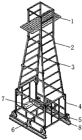
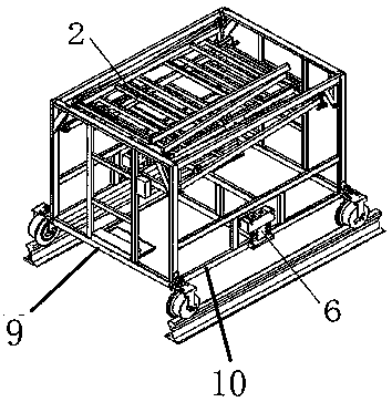
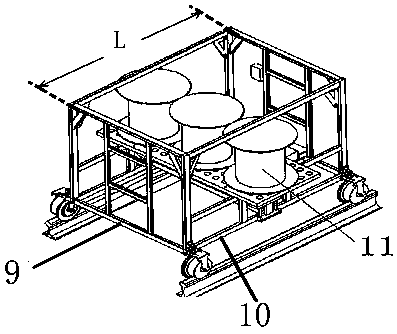
[0022] refer to figure 1 — Figure 9 , the catenary maintenance electric ladder car, including: a chassis, a working platform 1, a folding ladder body 2, a running device 5, the running device 5 is installed on the four bottom corners of the ladder seat 4, the chassis and the folding ladder body Ladder seat 4 is arranged between 2, and ladder seat 4 is fixed on the chassis, and the lower end of folding ladder body 2 is movably connected with the upper end of ladder seat 4;

[0023] The chassis is also equipped with a stabilizing device 6, and the stabilizing device 6 includes: a mounting seat 31, a permanent magnet 32, a positioning wheel 33, and the permanent magnet 32 ​​and the positioning wheel 33 are installed inside the mounting seat 31, and the positioning wheel 33 is installed on the permanent magnet 32 On both sides, the stabilizing device mounting base 31 is installed on the chassis longitudinal bar 10 through the pin hole 34 and the pin shaft, and can rotate around ...


PUM


Abstract

The invention discloses an overhead line system maintenance electric ladder vehicle which comprises a chassis, an operating platform, a folding ladder body and walking devices. The walking devices areinstalled at the four bottom corners of a ladder base 4. The ladder base is arranged between the chassis and the folding ladder body and fixed to the chassis. The lower end of the folding ladder bodyis movably connected with the ladder base. A stabilizing device is arranged on the chassis, and comprises an installation base, a permanent magnet and positioning wheels, wherein the permanent magnetand the positioning wheels are installed in the installation base, the positioning wheels are installed on the two sides of the permanent magnet, and the installation base is installed on the chassisand can swing round a pin shaft. In the working state, the ladder body is shortened in height, low in gravity center and high in stability; the positioning wheels are supported on rails, the permanent magnets provide constant downward pressure, the ladder body is stable, and operating is safe; in the walking state, the ladder body is folded up, the installation base upward swings and turns over,the effect of magnetic force is eliminated, running is easy and saves energy, operations are easy and save labor, people can rest hands on a frame when moving together with the ladder vehicle, runningis safe, and the speed is increased to 10 km/h.

Description

technical field [0001] The invention relates to equipment for installing and maintaining a catenary for railway transportation, in particular to an electric ladder car for catenary maintenance. Background technique [0002] At present, the quality and working status of the catenary will directly affect the transportation capacity of the electrified railway and the safety of the vehicles. Therefore, regular maintenance and inspection of the catenary is required. At present, there are mainly two types of maintenance equipment for the catenary, one is contactor The net inspection vehicle belongs to the large-scale railway maintenance machinery, and the other type is a small catenary maintenance ladder vehicle. These two types of vehicles have their own advantages and disadvantages and can be used to complement each other. The present invention belongs to the small catenary maintenance ladder vehicle. [0003] Commonly used small catenary maintenance ladder cars are generally op...

Claims


Application Information

Patent Timeline
Patent Type & Authority Applications(China)
IPC IPC(8): B60M1/28B61D15/00E06C1/397E06C1/383E06C7/42
CPCB60M1/28B61D15/00E06C1/383E06C1/397E06C7/42
Inventor 董升顺
Owner 湖南亚太高岸铁路装备股份有限公司
Why Eureka
Try Eureka