Supercharge Your Innovation With Domain-Expert AI Agents!

Hydraulic drive reciprocation pump

A reciprocating pump and hydraulic technology, applied to liquid fuel engines, pumps, piston pumps, etc., can solve the problems of easy wear of moving parts, complex mechanical structure, and inability to automatically reversing, and achieve low maintenance costs, simple control methods, and maintenance The effect of cost reduction

Active Publication Date: 2018-06-15
SHANGHAI MICROPOWERS
View PDF5 Cites 3 Cited by
  • Summary
  • Abstract
  • Description
  • Claims
  • Application Information

AI Technical Summary

Problems solved by technology

The double-cylinder double-acting reciprocating pump of this structure adopts the motion principle of the crankshaft and connecting rod, and cannot automatically reversing.

Method used


Image

  • Hydraulic drive reciprocation pump
  • Hydraulic drive reciprocation pump
  • Hydraulic drive reciprocation pump

Examples


Embodiment 1

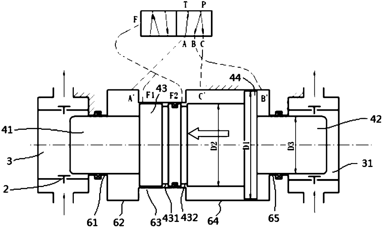
[0050] like figure 2 , image 3 , Image 6 as well as Figure 7 As shown, this embodiment discloses a technical solution of a hydraulically driven reciprocating pump, including: a piston assembly 4, a first pump body 3, a second pump body 31, a piston housing 6 and a hydraulic system (not shown in the figure).

[0051] The first pump body 3 and the second pump body 31 are respectively located on two sides of the piston housing 6 , and the piston assembly 4 is arranged to slide in the piston housing 6 . Both sides of the pump body are connected with a water inlet cavity 1 and a water outlet cavity 5, and the communication and sealing between the pump body and the water inlet cavity 1 and the water outlet cavity 5 are controlled by a one-way valve 2 .

[0052] The piston assembly 4 includes a first action part 41, a first drive part 43, a second drive part 44 and a second action part 42 arranged in sequence, and the diameters are D3, D2, D1, D3 respectively, and the size rel...

Embodiment 2

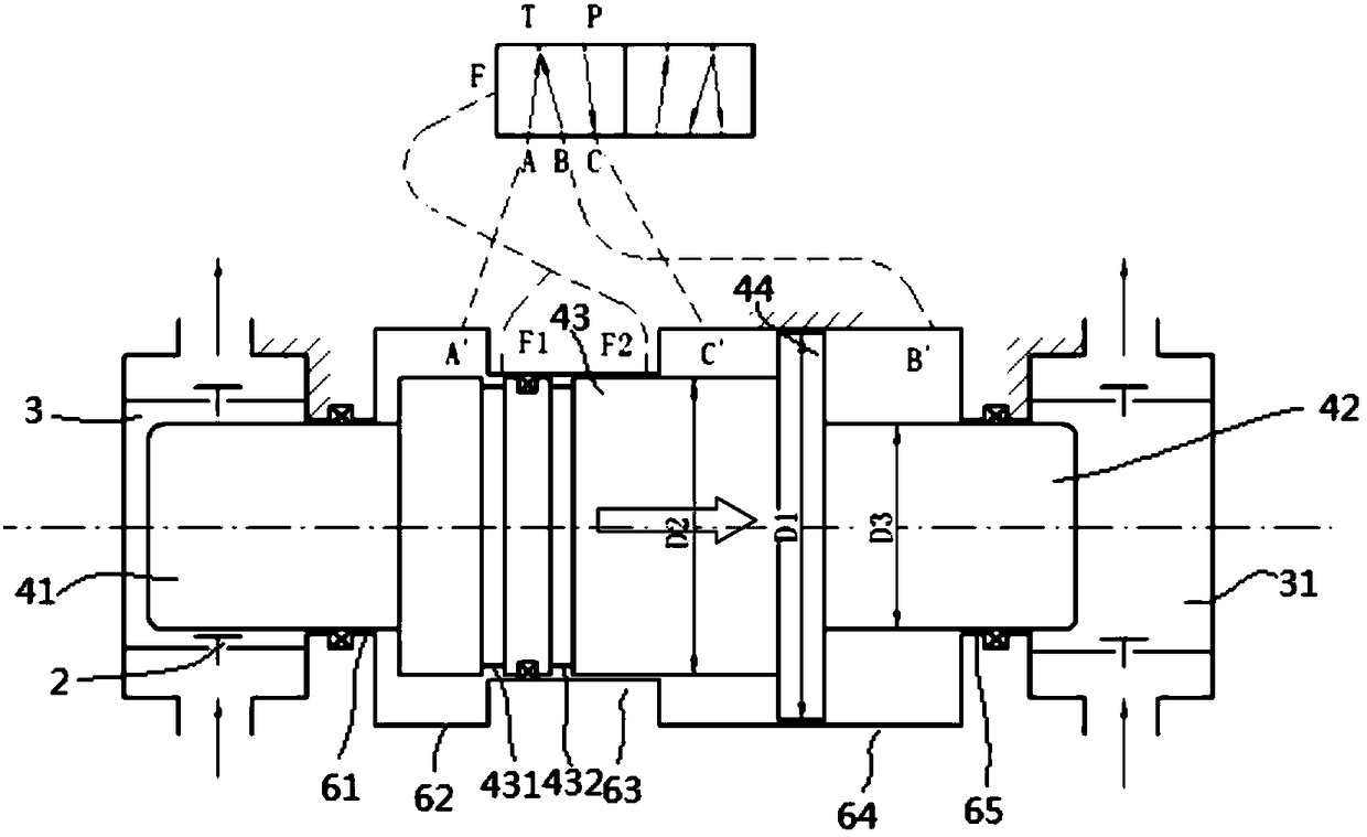
[0060] like figure 2 and image 3 As shown, on the basis of the first embodiment, the reversing valve 7 is a two-position five-way valve. It is equipped with T oil port, P oil port, A oil port, B oil port and C oil port. The hydraulic system feeds low-pressure oil into T port and high-pressure oil into P port; The chambers are connected, the B oil port is connected with the B' chamber, and the C oil port is connected with the C' chamber. in:

[0061] like figure 2 As shown, the reversing valve 7 is in the right position, the T port is connected with the A port, that is, the A' chamber is connected with low-pressure oil, and the P port is connected with the B port and the C port respectively, that is, the B' chamber Chamber and C'chamber lead to high-pressure oil. At this moment, the state of the first predetermined working condition in the first embodiment is realized.

[0062] like image 3 As shown, in the left position of the reversing valve 7, the T port is connec...


PUM


Abstract

The invention discloses a hydraulic drive reciprocating pump, which comprises a piston assembly, a pump body, a piston shell and a hydraulic system. The pump body is connected with an inlet pipeline and an outlet pipeline; the piston assembly arranged in the piston shell moves in a reciprocating way and is acted on the pump body; the piston assembly divides the piston shell into a first chamber, asecond chamber and a third chamber separated from each other; the hydraulic system communicates with the first chamber, the second chamber and the third chamber through a reversing valve, so that hydraulic oil is fed; low pressure oil is fed into the first chamber; high pressure oil is fed into the second chamber; the reversing valve can actuate to feed high pressure oil into the third chamber ata first preset working condition and can actuate to feed low pressure oil into the third chamber at a second preset working condition; and a composite force direction of the hydraulic oil applied onthe piston assembly under the first preset working condition is opposite to a composite force direction under the second preset working condition. A piston moves in a reciprocating way through hydraulic drive, so that a pumping action of the reciprocating pump is realized; and the hydraulic drive reciprocating pump is compact in structure, less in quick-wear parts, and low in operation cost.

Description

technical field [0001] The invention relates to the technical field of pumps, in particular to a hydraulically driven reciprocating pump. Background technique [0002] The double-cylinder double-acting reciprocating pump has already come out in the 19th century and has been widely used. However, due to the low speed and small displacement of this reciprocating pump, it is gradually replaced by centrifugal pumps and rotary pumps. attached in the manual figure 1 Shown is the working principle of the traditional double-cylinder double-acting piston pump. Driven by the power source on the right side of the figure, the piston of the reciprocating pump reciprocates left and right, and the working chamber on the side where the piston moves forward is compressed to pump the medium. The working chamber on the other side is suctioned. The "T"-shaped element in the figure is a one-way valve, which will automatically open or close with the movement of the piston. The double-cylinder...

Claims


Application Information

Patent Timeline
IPC IPC(8): F04B9/113F04B49/22F04B53/00F04B53/10F04B53/14
CPCF04B9/113F04B49/22F04B53/00F04B53/10F04B53/14
Inventor 黄嘉镔沈陆飞李天宇张锡杰刘雁飞梁燕卢平戴旭东
Owner SHANGHAI MICROPOWERS
Features
  • R&D
  • Intellectual Property
  • Life Sciences
  • Materials
  • Tech Scout
  • Unparalleled Data Quality
  • Higher Quality Content
  • 60% Fewer Hallucinations
Learn More