Crankshaft vibration reducer and control method of crankshaft vibration reducer

A crankshaft shock absorber and control method technology, applied in the direction of shock absorber, spring/shock absorber design features, spring/shock absorber, etc., can solve the problem of complex structure of shock absorber, difficulty in later maintenance, difficult control, etc. problem, to achieve the effect of simple structure, low control difficulty and stable working process of the crankshaft

Active Publication Date: 2018-06-15
WEICHAI POWER CO LTD
View PDF7 Cites 8 Cited by
  • Summary
  • Abstract
  • Description
  • Claims
  • Application Information

AI Technical Summary

Problems solved by technology

[0007] The object of the present invention is to provide a crankshaft damper and a control method for the crankshaft damper, which are used to solve the problem that the shock absorber in the prior art has complex structure, high cost, difficult control, difficult post-maintenance, and liquid leakage. The problem

Method used


Image

  • Crankshaft vibration reducer and control method of crankshaft vibration reducer
  • Crankshaft vibration reducer and control method of crankshaft vibration reducer
  • Crankshaft vibration reducer and control method of crankshaft vibration reducer

Examples


Embodiment Construction

[0047] The technical solutions of the present invention will be further described below in conjunction with the accompanying drawings and through specific implementation methods.

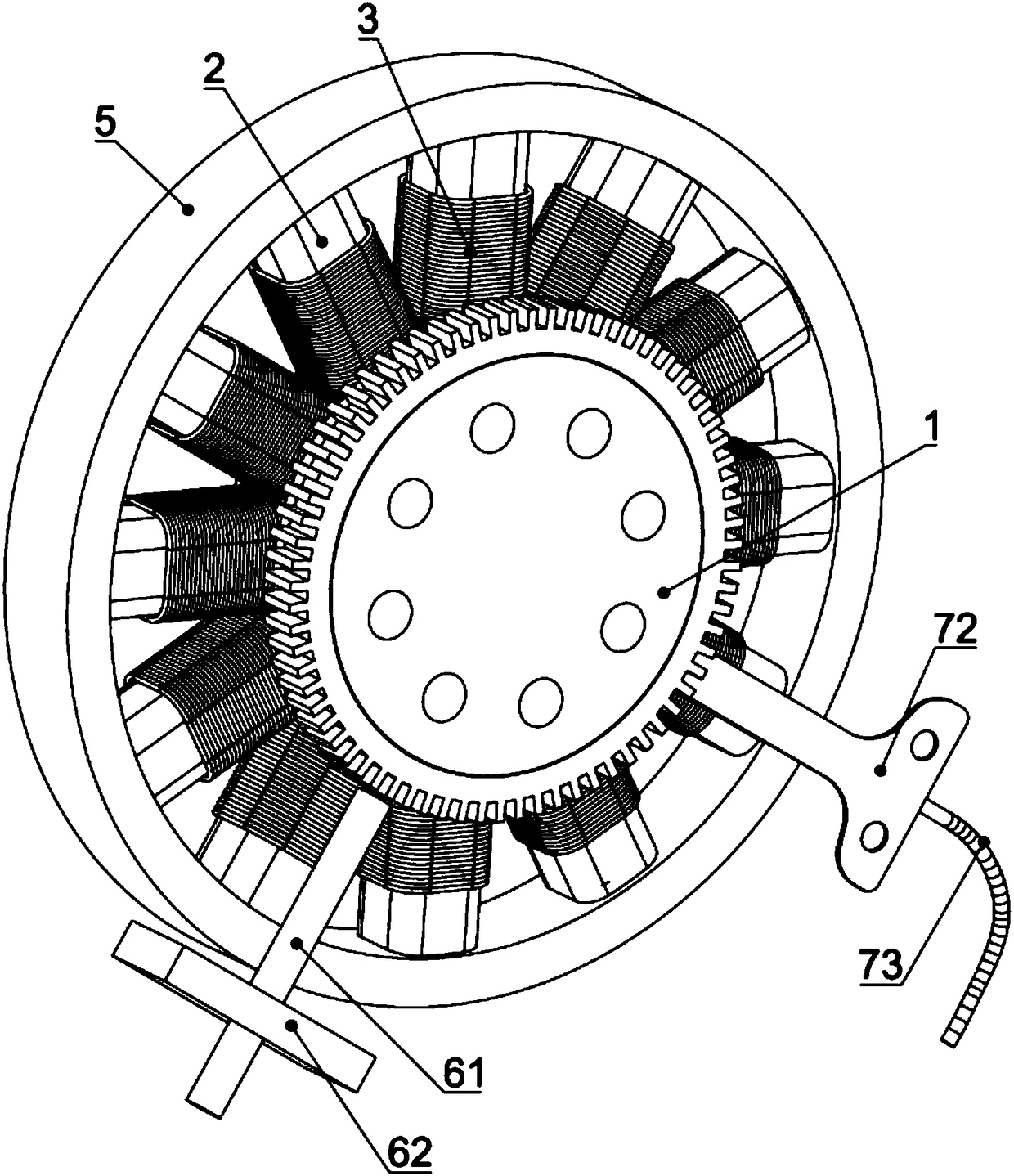
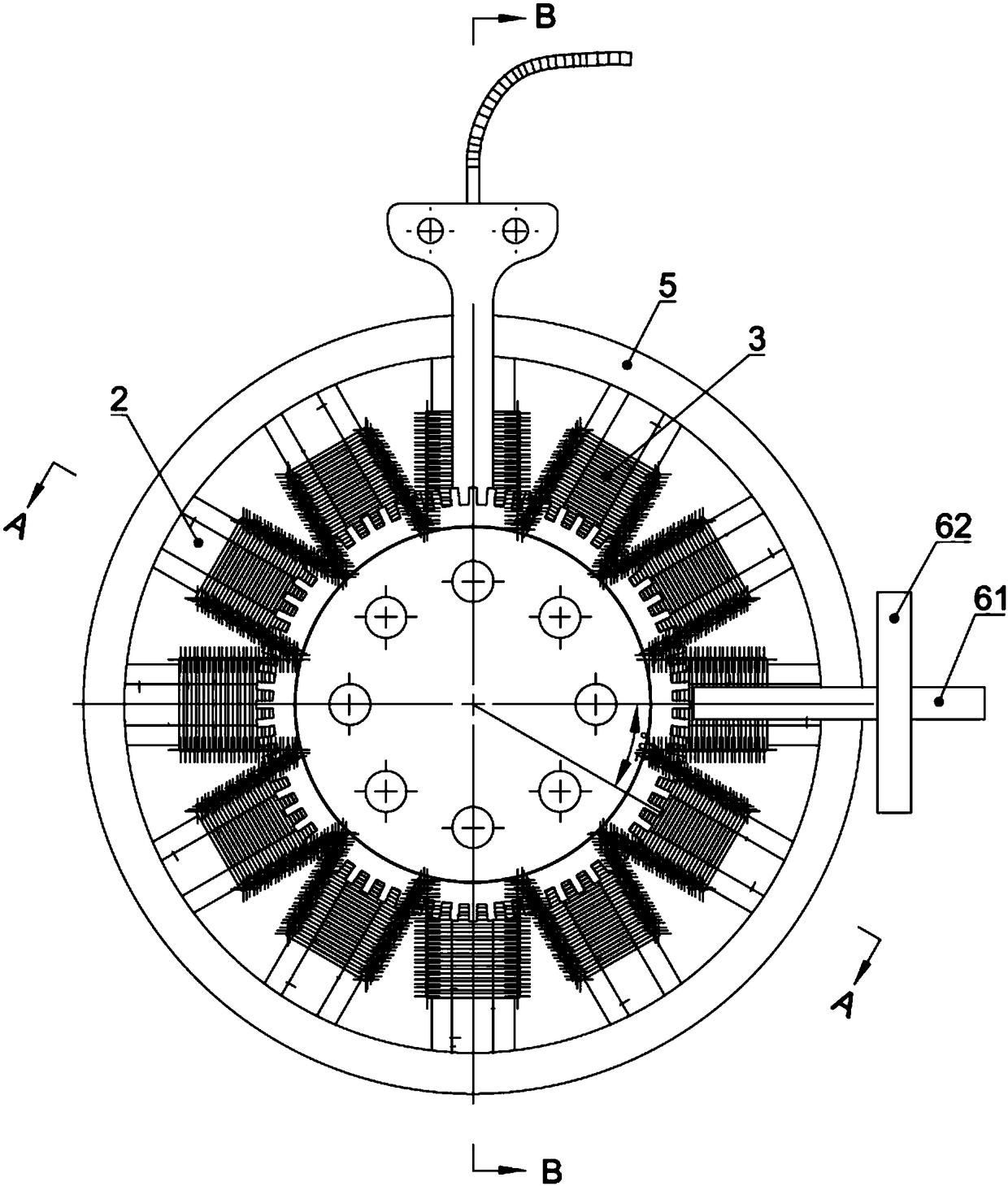
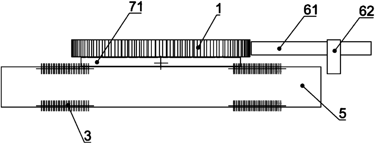
[0048] Such as Figure 1-6 As shown, a crankshaft damper is provided in this embodiment, and the crankshaft damper includes a chainring assembly 1, a cylindrical member 2, an electromagnetic coil 3, an electromagnetic assembly 4, an outer ring 5, a control unit and a wire assembly 7 . Among them, the toothed plate assembly 1 includes a toothed plate 11 and a cylinder 12, the toothed plate 11 is connected to the crankshaft; the cylinder 12 and the toothed plate 11 are fixedly connected by eight screws arranged circumferentially on the cylinder 12, and the toothed plate 11 is connected on the crankshaft, therefore, the chainring 11 and the cylinder 12 can rotate together with the crankshaft.

[0049] The above cylindrical member 2 is centered on the center of the cylinder 12 and is circumferentially...


PUM


Abstract

The invention relates to the technical field of vehicle torsional vibration dampers, and discloses a crankshaft vibration reducer. The crankshaft vibration reducer comprises a tooth disc module, a cylindrical piece, an electromagnetic coil and an electromagnetic module, wherein the tooth disc module is connected to a crankshaft; the cylindrical piece is peripherally arranged on the tooth disc module with the center of the tooth disc module as center; the electromagnetic coil is wound on the outer wall of the cylindrical piece; and the electromagnetic module is arranged in the cylindrical piece, and can perform a reciprocating motion along the cylindrical piece. The crankshaft vibration reducer solves the problems of complicated structure, high cost, high control difficulty, difficult latermaintenance and liquid leakage in a vibration reducer in the prior art. The invention further provides a control method of the crankshaft vibration reducer; the crankshaft vibration reducer is adopted; the crankshaft drives the tooth disc module and the electromagnetic module to rotate; and a current value in the electromagnetic coil under corresponding rotating speed is controlled according to the rotating speed.

Description

technical field [0001] The invention relates to the technical field of automobile torsional vibration dampers, in particular to a crankshaft damper and a control method for the crankshaft damper. Background technique [0002] When the reciprocating piston internal combustion engine is working, the crankshaft system will generate torsional vibration, which will cause premature damage to the crankshaft and related parts, affect the safe and reliable operation of the internal combustion engine, and generate excessive noise and vibration at the same time. In order to solve the above problems, a shock absorber is generally installed on the shafting of the engine to reduce or eliminate the torsional vibration of the crankshaft, hereinafter referred to as torsional vibration. [0003] In the prior art, the torsional vibration damper combined with silicone oil and rubber is usually installed on the shafting, but this kind of torsional vibration damper belongs to purely mechanical co...

Claims


Application Information

Patent Timeline
Patent Type & Authority Applications(China)
IPC IPC(8): F16F15/18F16F6/00
CPCF16F6/00F16F15/002F16F15/18F16F2222/06F16F2230/18F16F2232/02
Inventor 范明德任丰琳董杰
Owner WEICHAI POWER CO LTD
Why Eureka
Try Eureka