Connection structure of vacuum pipeline
A vacuum pipeline and connection structure technology, which is applied to pipeline systems, pipes/pipe joints/fittings, expansion compensation devices for pipelines, etc., can solve the problems of vacuum pipeline structure leakage, poor bearing capacity, poor sealing performance, etc., to achieve Avoid leakage, facilitate maintenance and handling, and improve the effect of safety factor
- Summary
- Abstract
- Description
- Claims
- Application Information
AI Technical Summary
Problems solved by technology
Method used
Image
Examples
Embodiment 1
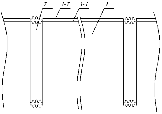
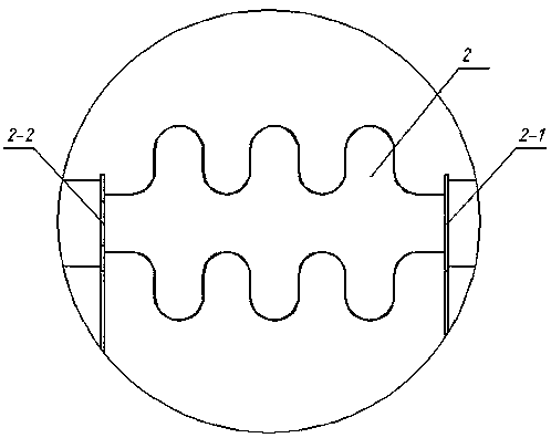
[0045] Such as Figure 1~2 Shown is a connection structure of vacuum pipelines, the vacuum pipelines are formed by connecting multiple single-section pipelines 1, in order to prevent thermal expansion and contraction of the vacuum pipelines, every two adjacent pipelines are connected by expansion joints.
[0046]The single-section pipeline 1 is a sandwich structure, including an upper panel 1-2 and a lower panel 1-1, and a sandwich layer is arranged between the panels, and the sandwich layer includes a plurality of corrugated boards arranged at intervals between the two panels. The board is vertically arranged between the two panels, and the corrugated board has a certain thickness, which can increase the connection area with the panels. The corrugated board is soldered to the two panels. Both the upper panel 1-2 and the lower panel 1-1 are made of stainless steel, and the brazing filler metal is copper brazing filler metal.
[0047] The expansion joint is an inner and outer...
Embodiment 2
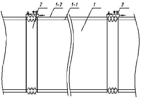
[0050] Such as Figure 3-4 As shown, the difference from Example 1 is that on the basis of Example 1, the two adjacent single-section pipelines 1 connected to the expansion joint are also connected by a pipeline with a valve group 3, and the pipeline with a valve group 3 is connected There is a section of shrinkable pipeline 3-2 to change with the thermal expansion and cold contraction of the vacuum pipeline.
[0051] There is an electric valve 3-1 on the pipeline 3 with valve group, and the connection or disconnection between the two single-section pipelines 1 is realized through the closing or disconnection of the electric valve 3-1; one side of the electric valve 3-1 is provided with Vacuuming device, an electric vacuum valve 3-3 is arranged at the connection between the vacuuming device and the pipeline 3 with valve group. By opening the electric valve 3-1 and the electric vacuum valve 3-3, the interlayer of two adjacent single-section pipelines 1 can be vacuumed simultan...
Embodiment 3
[0053] Such as Figure 5 As shown, the difference from Embodiment 2 is that the first electric valve 3-43-1 is provided on the side of the valve group pipeline 3 close to one single-section pipeline 1, and the first electric valve 3-43-1 is provided on the side close to the other single-section pipeline 1. Two electric valves 3-53-1, a vacuuming device is arranged between the first electric valve 3-43-1 and the second electric valve 3-53-1, and an electric vacuum is installed at the connection between the vacuuming device and the pipe with valve group 3 Valve 3-3, by opening the first electric valve 3-43-1, the second electric valve 3-53-1 and the electric vacuum valve 3-3, the interlayer of two adjacent pipelines can be vacuumed at the same time; or by selectively opening the first electric valve An electric valve 3-43-1 or a second electric valve 3-53-1 simultaneously open the electric vacuum valve 3-3 to vacuumize the interlayer of a certain single-section pipeline 1.
PUM
 Abstract
Description
Claims
Application Information
 - R&D
- Intellectual Property
- Life Sciences
- Materials
- Tech Scout
- Unparalleled Data Quality
- Higher Quality Content
- 60% Fewer Hallucinations
Browse by: Latest US Patents, China's latest patents, Technical Efficacy Thesaurus, Application Domain, Technology Topic, Popular Technical Reports.
© 2025 PatSnap. All rights reserved.Legal|Privacy policy|Modern Slavery Act Transparency Statement|Sitemap|About US| Contact US: help@patsnap.com


