LED light source for LED lamp and manufacturing method

A technology of LED light source and LED lamp, applied in the field of LED light source, can solve the problems of increasing the difficulty of thinning the display and increasing the manufacturing cost of the display, and achieve the effects of rapid heat dissipation, easy large-scale manufacturing, and simple structure

Pending Publication Date: 2018-06-15
深圳市中科燧承科技有限公司
View PDF7 Cites 0 Cited by
  • Summary
  • Abstract
  • Description
  • Claims
  • Application Information

AI Technical Summary

Problems solved by technology

These additional heat dissipation mechanisms increase the manufacturing cost of the display and increase the difficulty of thinning the display

Method used


Image

  • LED light source for LED lamp and manufacturing method
  • LED light source for LED lamp and manufacturing method
  • LED light source for LED lamp and manufacturing method

Examples


Embodiment Construction

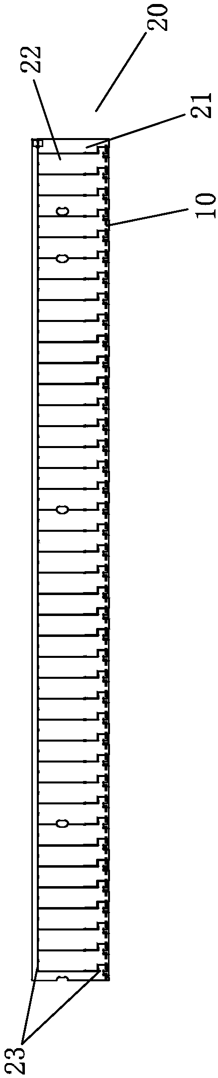
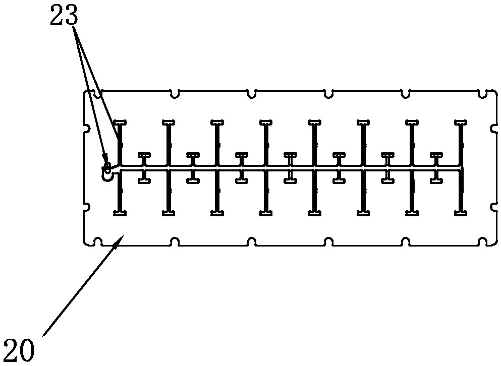
[0132] Refer to the attached Figure 1 to Figure 6 and Figure 9 to Figure 14As shown, the LED light source according to the preferred embodiment of the present invention is clarified, which can be used as a side-entry LED light source for a display, a light box or a light source for an LED lamp, etc., wherein the LED light source includes a group of LED illuminants 10, a The conductive heat dissipation plate 20 and an insulating heat dissipation layer 30 , wherein the conductive heat dissipation plate has two side surfaces 201 , wherein the LED illuminant 10 and the insulating heat dissipation layer 30 are both arranged on the same side surface 201 of the conductive heat dissipation plate. Preferably, the insulating heat dissipation layer 30 is arranged on both sides (sides 201 ) of the conductive heat dissipation plate 20 , so that both sides of the conductive heat dissipation plate 20 of the LED light source can be used to conduct heat to the insulating heat dissipation lay...


PUM


Abstract

The invention provides a novel LED light source. The LED light source has the effect of being higher in heat dissipation efficiency and is suitable for LED lamps and the like.

Description

technical field [0001] The invention relates to an LED light source, in particular to an LED light source suitable for display side-entry backlight sources, light box light sources, LED lamps and other light sources. The invention further relates to a method for producing an LED light source. Background technique [0002] Common LED light sources generally include LED illuminants (LED light-emitting chips), printed circuits, substrates, and heat sinks. LED illuminants are mostly composed of light-emitting wafers composed of P-type semiconductors and N-type semiconductors, brackets for supporting the wafers, and packaging materials for packaging the light-emitting wafers, such as epoxy resin. In order to better fix the light-emitting chip at a preset position and supply power to the light-emitting chip, the LED illuminant may also include wires connecting the light-emitting chip and the bracket, conductive glue for fixing the light-emitting chip, and the like. LED light sou...

Claims


Application Information

Patent Timeline
Patent Type & Authority Applications(China)
IPC IPC(8): F21K9/20F21K9/90F21K9/61F21V23/00F21V23/06F21V29/503F21V29/70H01L33/64F21Y115/10
CPCH01L33/641H01L33/642F21K9/20F21K9/61F21K9/90F21S8/00F21V19/001F21V23/00F21V23/06F21V29/503F21V29/70F21V29/85F21V29/89F21V2200/20F21Y2115/10
Inventor 蔡鸿
Owner 深圳市中科燧承科技有限公司
Why Eureka
Try Eureka